Parameter No. Parameter name
P030 1st PM Motor Starting Method
P060 1st PM Motor Armature Resistance
P061 1st PM Motor d-axis Inductance
P062 1st PM Motor q-axis Inductance
P063 1st PM Motor Induced Voltage Ke
P064 1st PM Motor Iron Loss
P065 1st PM Motor d-axis Inductance Magnetic Saturation Correction
P074 1st PM Motor Reference Current at Starting
P085 1st PM Motor Flux Limitation Value
P087 1st PM Motor Reference Current for Magnetic Pole Detection
P090 1st PM Motor Overcurrent Protection Level
P095 1st PM Motor Magnetic Pole position Offset
d080 1st PM Motor Magnetic Pole Position Pull-in Frequency
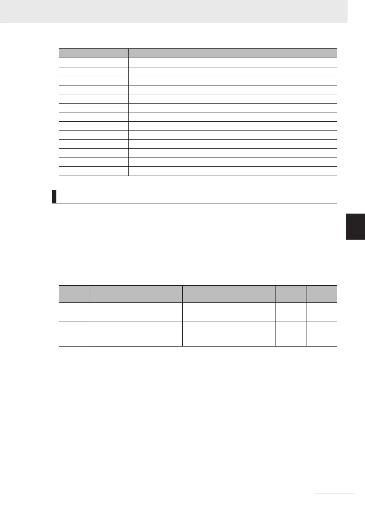
Forward RUN Command (FW) and Reverse RUN Command (RV)
• To input the forward RUN and reverse RUN commands via the control circuit terminals, allocate “98:
FW” and “99: RV” to Input Terminal [DI6] Function Selection (E98) and Input T
erminal [DI7] Function
Selection (E99). FW (forward rotation) and RV (reverse rotation) can be set to only Input Terminal
[DI6] Function Selection (E98) and Input Terminal [DI7] Function Selection (E99).
• Set “1: External signal (digital input)” to 1st RUN Command Selection (F02) and 2nd RUN Com-
mand Selection (E102).
• If all assigned terminals to which the same RUN command (FW or RV) is assigned to input termi-
nals [DI6] and [DI7] are ON, the function is handled as ON.
Parame-
ter No.
Function name Data
Default
data
Unit
F02/E102 1st RUN Command Selection/2nd
RUN Command Selection
*1
1: External signal (digital input)
2 -
E01 to
E05, E98,
E99
Input Terminal [DI1] Function Se-
lection to Input T
erminal [DI7] Func-
tion Selection
98: FW (forward rotation)
99: RV (reverse rotation) - -
*1. To enable switching to the 1st and 2nd control, allocate “12: SET (2nd control)” to either of input terminal
[DI1] to [DI7].
• When both FW and RV turn ON, operation is the same as when they are both OFF.
5 Basic Settings
5-55
M1 Series Standard Type User's Manual (I669)
5-9 Multi-function Input
5
5-9-1 Input Terminal Functions

 Loading...


