Parameter
No.
Function name Data Default data Unit
E20, E21
Output Terminal [DO1] Function Selection,
Output Terminal [DO2] Function Selection
0: RUN (Signal dur-
ing RUN)
35: RUN2 (Inverter
output in progress)
- -
E27
Output Terminal [ROA, ROB] Function Se-
lection
99 -
Related function
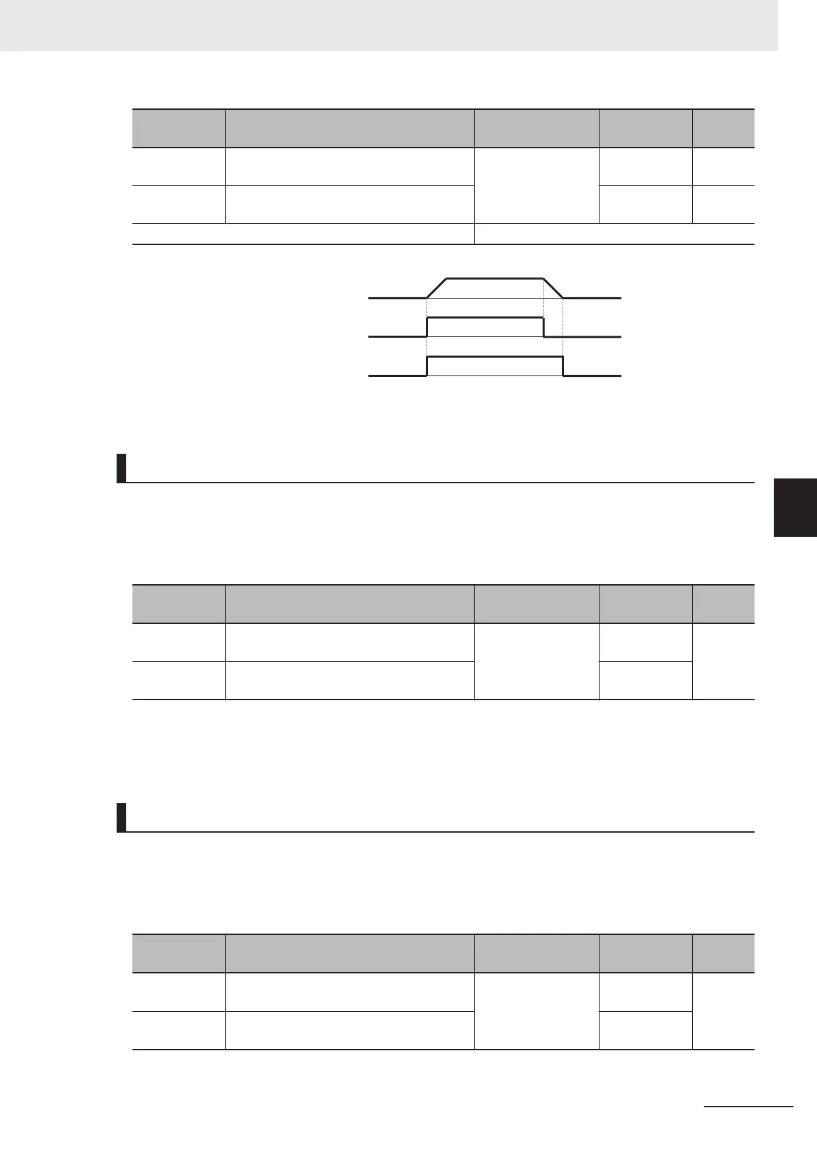
ON OFF
ON OFF
Outpu
t frequency
FW
RUN
Fig. OFF when at stop frequency and starting frequency or below
Forward Run Signal (FWR)
• This signal is output while the inverter performs forward operation.
• To output this signal, allocate “52: FWR (Forward run signal)” to Output Terminal [DO1] Function Se-
lection (E20), Output T
erminal [DO2] Function Selection (E21) or Output Terminal [ROA, ROB]
Function Selection (E27).
Parameter
No.
Function name Data Default data Unit
E20, E21
Output Terminal [DO1] Function Selection,
Output Terminal [DO2] Function Selection
52: FWR (Forward
run signal)
-
-
E27
Output Terminal [ROA, ROB] Function Se-
lection
99
• This signal is not output while the inverter performs reverse operation, when it is stopped or during
free-run. Note, however, that during control methods with sensor, judgment is performed based on
the speed detection value to output the signal even in free-run status.
Reverse Run Signal (RVR)
• This signal is output while the inverter performs reverse operation.
• To output this signal, allocate “53: R
VR (Reverse run signal)” to Output Terminal [DO1] Function Se-
lection (E20), Output Terminal [DO2] Function Selection (E21) or Output Terminal [ROA, ROB]
Function Selection (E27).
Parameter
No.
Function name Data Default data Unit
E20, E21
Output Terminal [DO1] Function Selection,
Output T
erminal [DO2] Function Selection
53: R
VR (Reverse
run signal)
-
-
E27
Output T
erminal [ROA, ROB] Function Se-
lection
99
5 Basic Settings
5-69
M1 Series Standard Type User's Manual (I669)
5-10 Multi-function output
5
5-10-1 Output Terminal Functions

 Loading...


