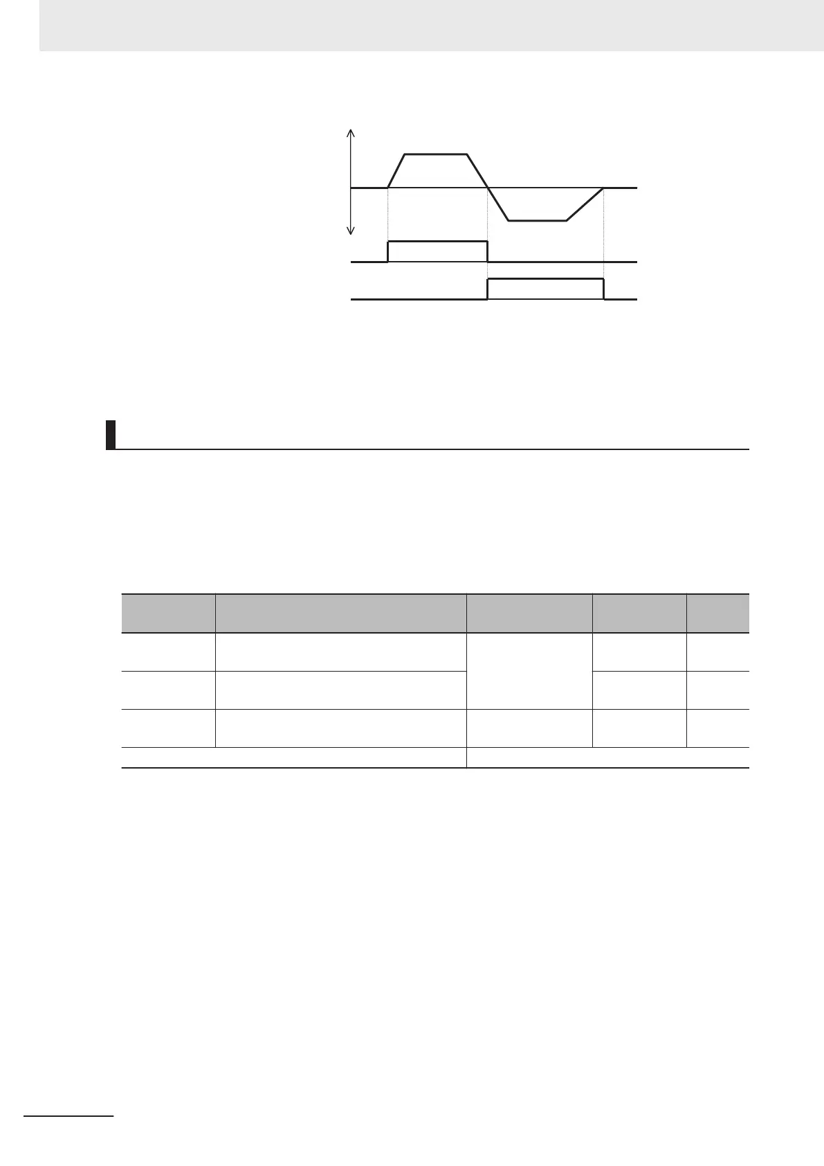
Outpu
t frequency
FWR
R
VR
R
ev
e
rse
Forward
• This signal is not output while the inverter performs forward operation, when it is stopped or during
free-run. Note, however, that during control methods with sensor, judgment is performed based on
the speed detection value to output the signal even in free-run status.
Frequency Arrival 1 (Constant Speed) (FAR1)
• This signal is output when the output frequency arrives at the frequency reference.
• To output this signal, allocate “1: F
AR1 (Frequency arrival 1 (constant speed))” to Output Terminal
[DO1] Function Selection (E20), Output Terminal [DO2] Function Selection (E21) or Output Terminal
[ROA, ROB] Function Selection (E27).
• The detection width of the frequency arrival signal is set at Frequency Arrival Detection Width
(FAR1/FAR2/FAR3/FDT3/FDT4) (E30).
Parameter
No.
Function name Data Default data Unit
E20, E21
Output Terminal [DO1] Function Selection,
Output Terminal [DO2] Function Selection
1: FAR1 (Frequency
arrival 1 (constant
speed))
- -
E27
Output T
erminal [ROA, ROB] Function Se-
lection
99 -
E30
Frequency Arrival Detection Width (FAR1/
FAR2/FAR3/FDT3/FDT4)
0.0 to 10.0 Hz
2.5 Hz
Related function
• When the output frequency is within the range of ± Frequency Arrival Detection Width (FAR1/FAR2/
FAR3/FDT3/FDT4) (E30) centering around the frequency reference, ON is output, and when it is
outside the range, this signal turns OFF.
•
During free-run or when the set frequency is less than the stop frequency, the RUN command turns
OFF, and turns OFF during a deceleration stop.
• The figure below shows an example of changing the frequency reference from frequency reference
(1) to frequency reference (2).
5 Basic Settings
5-70
M1 Series Standard Type User's Manual (I669)

 Loading...


