bit 0 : Startup direction of return-to-origin operation 0: Forward rotation direction, 1: Reverse ro-
tation direction
Return-to-origin operation starts in the direction defined by this bit regardless of the direc-
tion specified in the RUN command from the inverter.
bit 1 :
Direction of return-to-origin operation 0: Forward rotation direction, 1: Reverse rotation di-
rection.
This bit defines the direction of movement of the return-to-origin operation. When the re-
verse of the startup direction is set, ORL (origin search limit signal) is detected, then op-
eration is paused and is reversed.
bit 2 : Return-to-origin operation overtravel operation selection 0: Reversal by overtravel detec-
tion, 1: Stop by overtravel detection
This bit defines whether to stop or reverse operation when an overtravel is detected be-
fore ORL (origin search limit signal) is detected.
bit 3 : Origin limit switch timing selection 0: ON edge detection, 1: OFF edge detection
This bit defines whether or not to detect the limit switch at its ON edge or OFF edge.
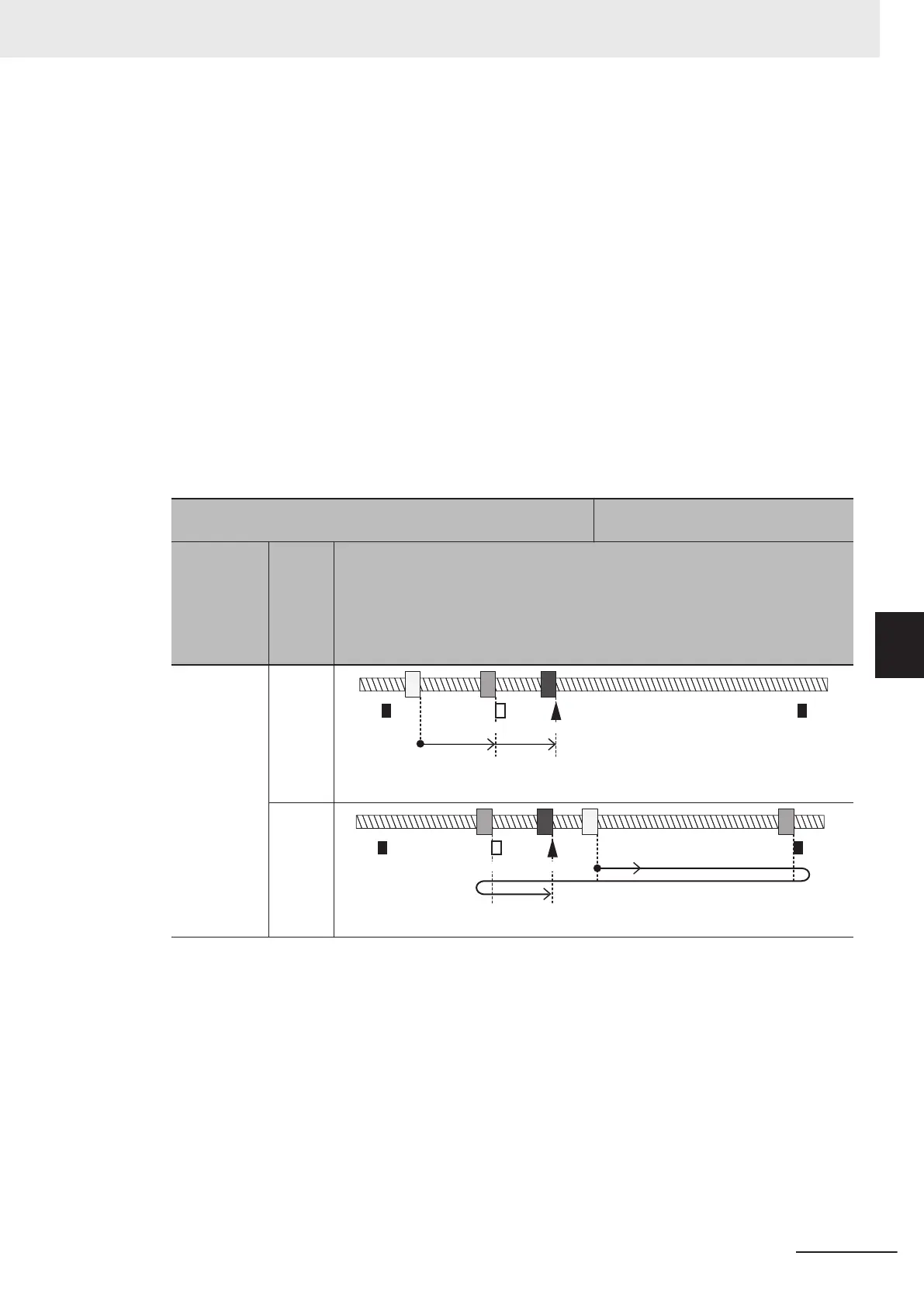
The figure below shows action according to the setting of the d209 parameter. In the figure, it is
assumed that bit 2 = 0 and reverse operation is performed at detection of an overtravel.
[d209 bit 1] Direction of return-to-origin operation 0: Forward
rotation direction (+)
When origin position > origin limit
switch position
Startup di-
rection of
return-to-
origin oper-
ation [d209
bit 0]
Initial
posi-
tion
Return-to-origin pattern diagram
0: + direction
- side
from
origin
limit
switch
+OT-OT
Origin LS
Origin
Direction of
return-to-origin operation +
Startup direction of
return-to-origin operation +
+ side
from
origin
limit
switch
+OT
-OT
Origin LS
Origin
Direction of return-to-origin operation +
Startup direction of
return-to-origin operation +
6 Vector Control and Applied Functions
6-45
M1 Series Standard Type User's Manual (I669)
6-7 Position Control
6
6-7-8 Basic Return-to-origin Operation

 Loading...


