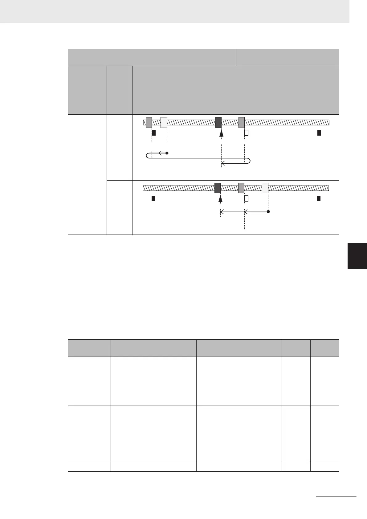
[d209 bit 1] Direction of return-to-origin operation 1: Reverse
rotation direction (+)
When origin position < origin limit
switch position
Startup di-
rection of
return-to-
origin oper-
ation [d209
bit 0]
Initial
posi-
tion
Return-to-origin pattern diagram
1: - direction
- side
from
origin
limit
switch
+OT
-OT
Origin LS
Origin
Direction of return-to-origin operation -
Startup direction of
return-to-origin operation -
+ side
from
origin
limit
switch
+OT-OT Origin LS
Origin
Direction of return-
to-origin operation -
Startup direction of
return-to-origin operation -
Homing Reference Signal Selection (d211), Reference Signal for Homing
Offset (d212)
The reference signal for homing is to switch from the homing frequency to the homing creep fre-
quency. The reference signal for homing starts incrementing of the homing offset. Ordinarily, the
signal of the origin limit switch is taken as the reference signal for homing and the Z phase signal is
taken as the reference signal for homing of
fset (factory default). When return-to-origin is configured
using other signals, select the reference signal for homing and reference signal for homing offset
according to the table below. When Reference Signal for Homing Offset (d212) is set to other than
“0: Z pulse of position encoder”, the reference signal for homing is not included in the configuration,
and so the Homing Reference Signal Selection (d211) setting is disabled.
Parameter No. Function name Data
Default
data
Unit
d211
Homing Reference Signal Se-
lection
0: Z phase
1: Origin limit input (ORL)
2: Overtravel input in the posi-
tive direction (FOT)
3: Overtravel input in the nega-
tive direction (ROT)
1 -
d212
Reference Signal for Homing
Offset
0: Z phase
1: Origin limit input (ORL)
2: Overtravel input in the posi-
tive direction (FOT)
3: Overtravel input in the nega-
tive direction (ROT)
4: Stopper (Hit and stop)
0 -
d214
Creep Frequency 0.1 to 590.0 Hz 0.5 Hz
6 Vector Control and Applied Functions
6-47
M1 Series Standard Type User's Manual (I669)
6-7 Position Control
6
6-7-8 Basic Return-to-origin Operation

 Loading...


