OFF
OFF
OFF
OFF
OFF
ON
ON ON ON
ON
OFF
ON
O
N
ON
ON
ON
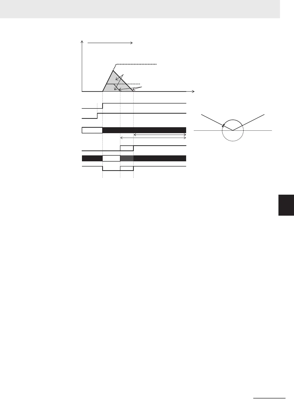
Position controlFrequency
[FW]
[RV]
[ORT]
[POK]
Servo lock status
Command
direction = CW
Current position
Time
Stop target position
Stop required pulse
Homing Frequency/O
rientation Frequency [d213] (Large)
Deceleration Time for Homing/Orientation [d215]
Homing Frequency/Orientation Frequency [d213] (Small)
[P-SEL]
Inverter
output status
Brake status
Nearest direction
(CCW)
Acceleration Time
[F07, E10,
E12, E14]
(2)
(2)
(2)
(1)
When using the orientation function, vector control with speed sensor, by which speed feedback
control is performed by a machine shaft encoder, can be selected as the control mode when the
motor to machine shaft transmission gear ratio (speed reduction ratio) is (as a guideline) approx.
5x. In the case of vector control with speed sensor, servo lock operation is performed after a posi-
tioning stop, and, if external force is applied after the stop, resistance torque is generated in an at-
tempt to hold the stop position.
On the other hand, when the machine shaft to motor shaft transmission gear ratio (speed reduction
ratio) is large, it will be dif
ficult to detect the motor speed at low-speed rotation, and machine per-
formance sometimes can no longer be sufficiently demonstrated unless an encoder with a large
number of pulses is used. On machines to which an encoder with a large number of pulses cannot
be attached or that have a large transmission gear ratio, use V/f control with speed sensor and not
vector control with speed sensor that performs speed feedback control from a machine shaft en-
coder. Servo lock operation is not possible in V/f control with speed sensor. When an external force
is applied after a stop, use a mechanical brake. Also, in V/f control with speed sensor, torque boost
sometimes must be adjusted or automatic torque boost sometimes must be set to generate torque
at ultra low speeds immediately before a stop.
6 Vector Control and Applied Functions
6-51
M1 Series Standard Type User's Manual (I669)
6-7 Position Control
6
6-7-11 Orientation
 Loading...


