EasyManuals Logo

Omron M1 Series User Manual

Omron M1 Series
808 pages
To Next Page IconTo Next Page
To Previous Page IconTo Previous Page
Page #479 background imageLoading...
Page #479 background image
OFFON
OFF
ON
OFF
ON
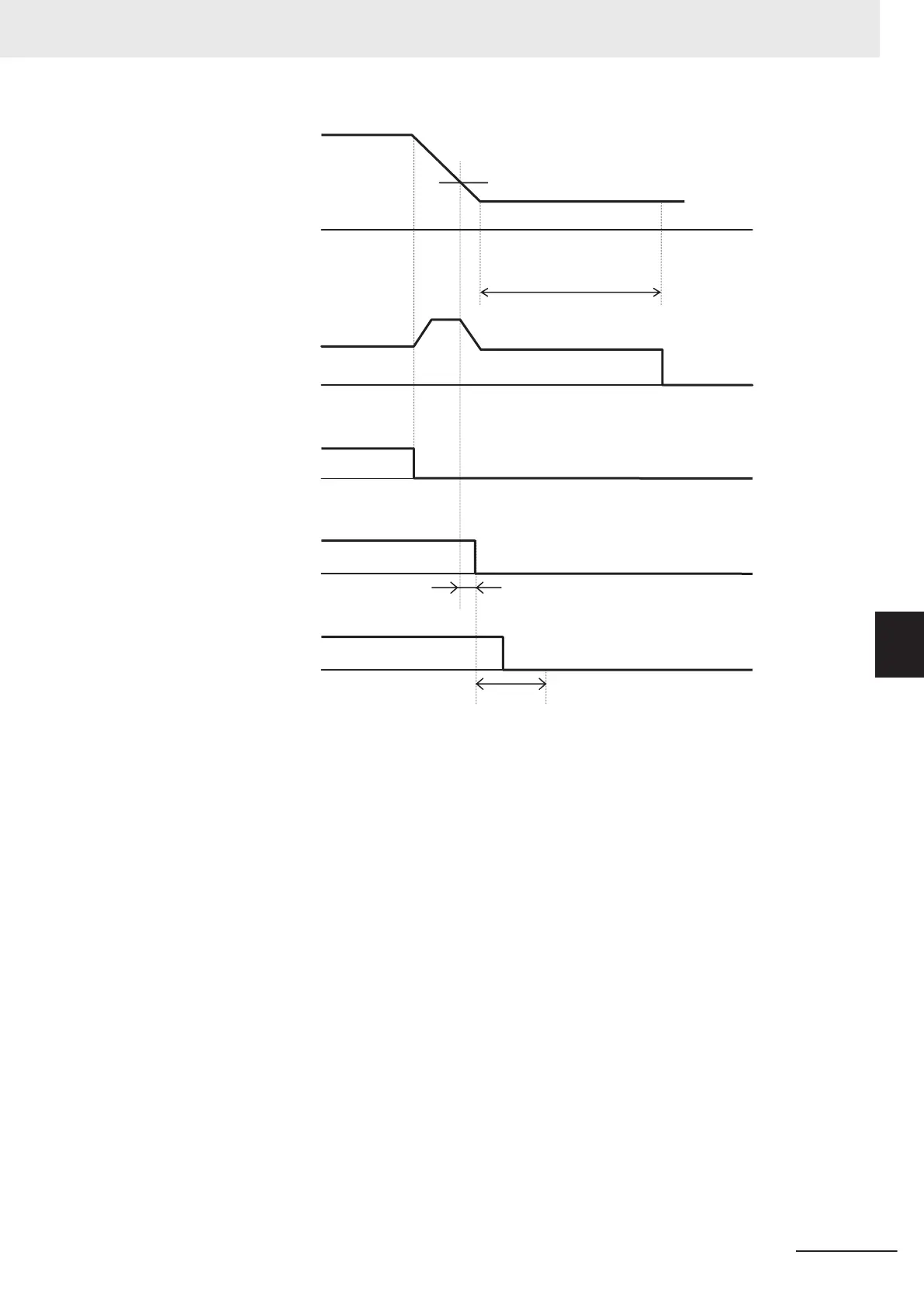
F25: 1st Stop Frequency
Output frequency
Output current
RUN command
J72: Brake Contro
l Brake-applied Timer
H180: Brake Error Detection Time
J71: Brake Control Brake-applied Frequency
V/f control Operation time chart at stop
F39: 1st Stop Frequency
Holding Time
Brake release signal
“BRK”
Brake confirmation signal
“BOK”
6 Vector Control and Applied Functions
6-73
M1 Series Standard Type User's Manual (I669)
6-9 Brake Control Function
6
6-9-1 Operation Sequence of Brake Control Function

Table of Contents

Questions and Answers:

Question and Answer IconNeed help?

Do you have a question about the Omron M1 Series and is the answer not in the manual?

Omron M1 Series Specifications

General IconGeneral
Input Voltage200-240V AC
Output Voltage3-phase 200 to 240 VAC
Protection FunctionsOvercurrent, Overvoltage, Undervoltage, Overheating, Short Circuit
CommunicationRS-485, Modbus RTU
EnclosureIP20
Cooling MethodFan Cooled
Operating Temperature-10°C to +50°C
Humidity5-95% (non-condensing)
AltitudeUp to 1000m
Frequency Range0.5-400 Hz
Storage Temperature-20°C to +65°C

Related product manuals