OFFON
OFFON
OFFON
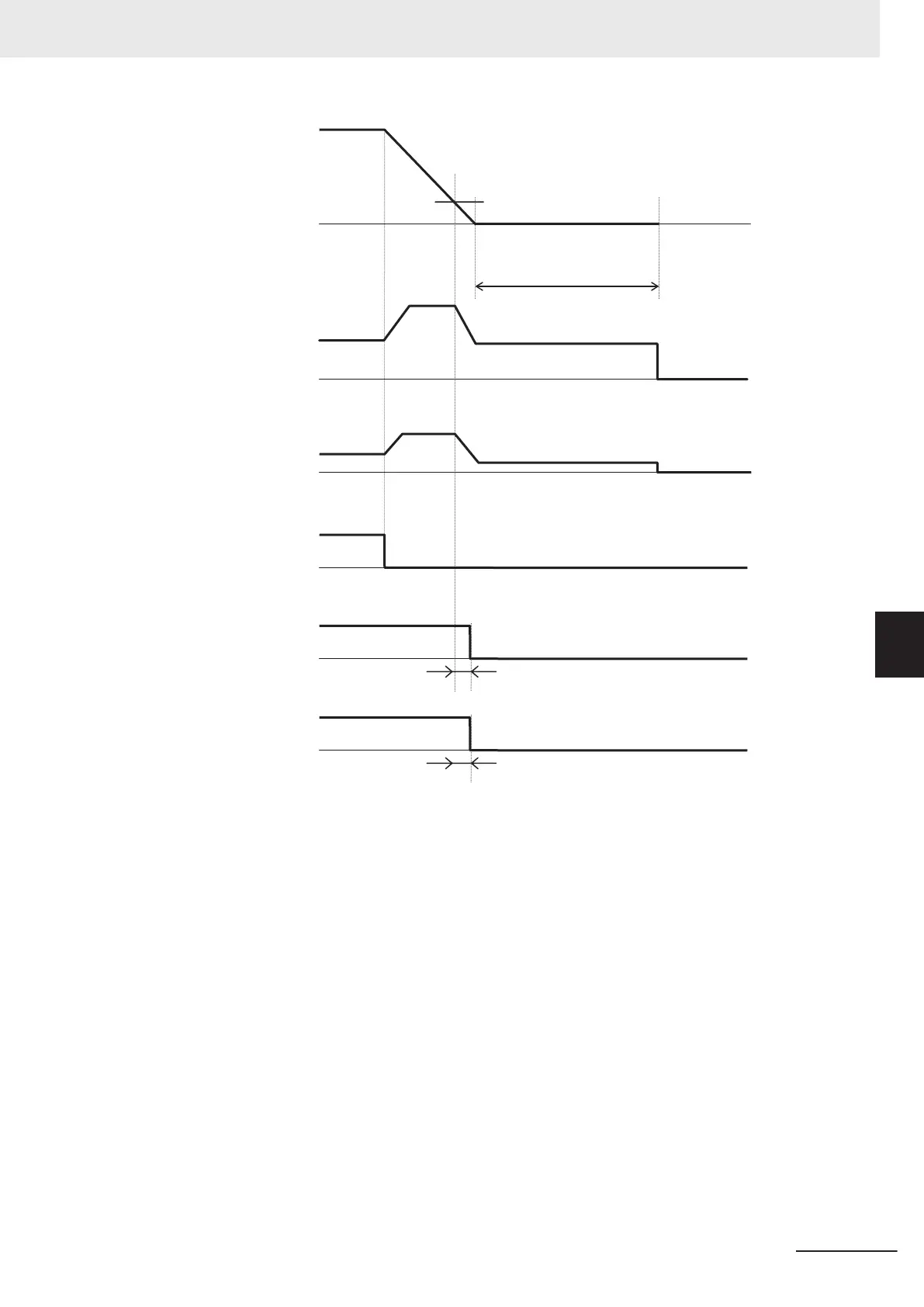
J71: Brake Control
Brake-applied Frequency
F25 = 0: 1st Stop Frequency
Output frequency
Output current
RUN command
Brake release signal
“BRK”
J72: Brake Control Brake-applied Timer
Brake confirmation signal
“BOK”
H180: Brake Error Detection Time
Vector control Operation time chart at stop
F39: 1st Stop
Frequency Holding Time
Torque command
Note
The above sequence chart shows an example where one of Input Terminal [DI1] Function Selection to Input
Terminal [DI7] Function Selection (E01 to E05, E98, E99) is set to “65: BOK (brake confirmation signal).”
At acceleration
1. When the RUN command is input, the inverter starts output.
2. When both the output current and output frequency (in V/f control) and the output current and
torque command (in vector control) reach the brake signal release level (J68, J69, J95), the in-
verter waits for the time set at Brake Control Brake-release Timer (J70) and then outputs the
brake release signal (E20, E21, E27 = 57: BRK).
3. After the brake release signal is output, the inverter waits for input of the brake confirmation sig-
nal (E01 to E05, E98, E99 = 65: BOK) for the time set at Brake Error Detection Time (H180).
If the brake confirmation signal is not input within the time set at H180, the inverter sets the out-
put terminal and outputs the brake error signal (E20, E21, E27 = 182: BER) and detects the
brake error (Er6).
6 Vector Control and Applied Functions
6-75
M1 Series Standard Type User's Manual (I669)
6-9 Brake Control Function
6
6-9-1 Operation Sequence of Brake Control Function

 Loading...


