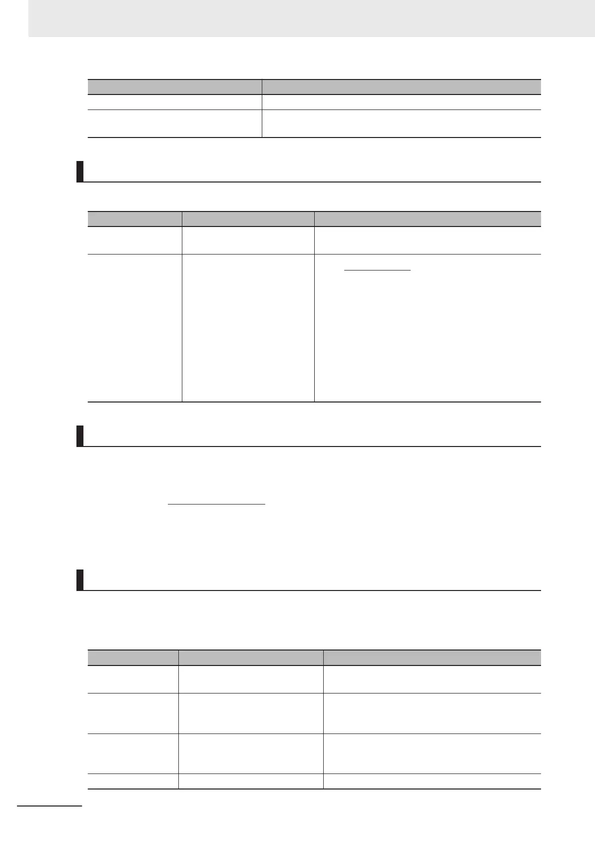
LSC-HLD Function
OFF Disabled (save operation not performed)
ON
Enabled (frequency reference after thick winding compensation is
saved)
Digital Setting
Set as follows to set the peripheral speed (feed speed) digitally in m/min.
Parameter No. Function name Description
E48
Operator Display Speed Moni-
tor Item Selection
5: Feed speed
E50
1st Frequency Conversion Co-
efficient
240π×a×r
1
p×b
K
S
=
K
S
: 1st Frequency Conversion Coefficient (E50)
p : Number of motor poles
a, b : Motor shaft - Winding shaft speed reduction ratio
(Rotation of winding shaft a occurs
when the motor shaft b rotates)
r1 : Radius of winding system
(Initial value before winding) (m)
Analog Setting
To set the peripheral speed (feed speed) by analog input, set analog input (0% to 100%) by the follow-
ing formula.
p × b × 100
240π × r1 × a × fmax
× V
Analog input (%) =
V: Peripheral speed (line speed) (m/min), fmax: 1st Maximum Output Frequency (F03)
Adjustment
Just like regular speed control, the speed command filter, speed detection filter, P gain, integral time,
and other parameters of the speed control system that controls peripheral speed to a constant speed
must adjusted.
Parameter No. Function name Description
d01
Speed Control 1 Speed Com-
mand Filter
Increase the filter constant when overshooting in re-
sponse to changes in the speed command is large.
d02
Speed Control 1 Speed Detection
Filter
Set a large filter constant to increase gain when the
speed detection signal contains ripple and the gain
of speed control cannot be raised.
d03
Speed Control 1 P Proportional
Gain
When running a motor at a speed in which hunting
occurs, lower the gain. When response is slow, in-
crease the gain.
d04 Speed Control 1 I Integral T
ime When response is slow, shorten the integral time.
6 Vector Control and Applied Functions
6-80
M1 Series Standard Type User's Manual (I669)

 Loading...