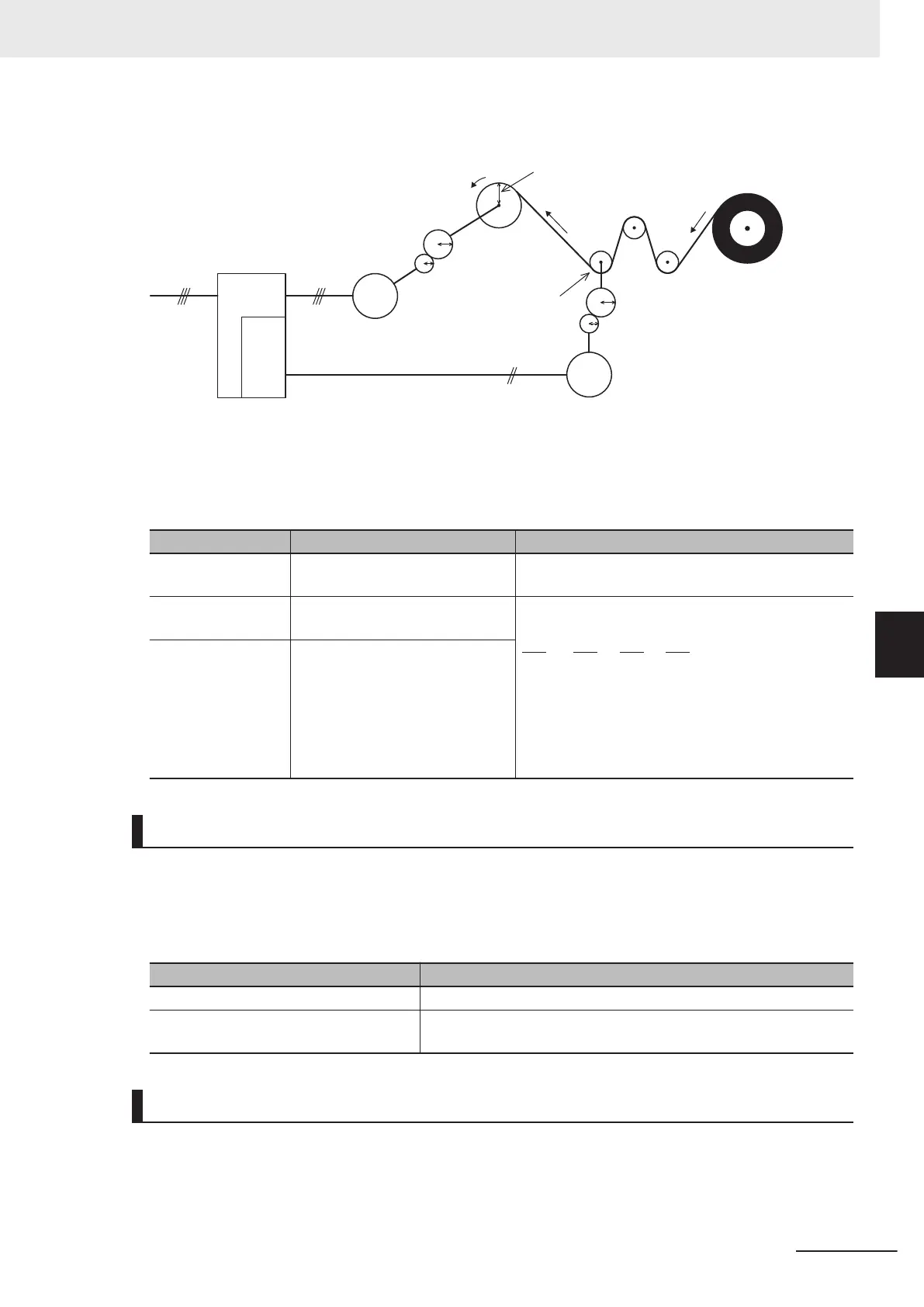
Drum
Motor
Inverter
Encoder
I/F card
Encoder
Winding system
(Thick winding)
Speed reduction ratio a : b
(Rotation of winding shaft a
through rotation of
motor shaft b)
Speed reduction ratio c :d
(Rotation of encoder shaft c
through rotation of
speed detection shaft d)
Phases A and B or Phase B
Radius of winding
system section r
1
Radius of speed
detection section r
2
Winding
direction
speed v
Speed v
u, v, wR, S, T
c
d
a
b
• Speed reduction ratio of motor shaft to winding shaft: a:b
• Speed reduction ratio of speed detection shaft to encoder shaft: c:d
• Radius of winding system section before winding: r1 [m]
•
Radius of speed detection section: r2 [m]
Parameter No. Function name Description
d15
Input Terminal [PIA][PIB] Encoder
Pulse Resolution
Set the number of encoder pulses in hexadecimal
[P/R]
d16
Input Terminal [PIA][PIB] Pulse
Scaling Factor Denominator
Speed reduction ratio of overall mechanical system
Set denominator coefficient (K1 = r1 × a × c) of d16
= speed reduction ratio
Set numerator coefficient (K2 = r2 × b × d) of d17 =
speed reduction ratio
d17
Input Terminal [PIA][PIB] Pulse
Scaling Factor Numerator
Canceling Line Speed Control
Line speed control can be canceled by the “Hz/LSC” signal. When line speed control is canceled, fre-
quency compensation by PI arithmetic calculation is set to zero. As a result, thick winding compensa-
tion is no longer carried out and winding speed increases. Use this feature to temporarily stop control,
for example, to correct thread breakage.
Hz/LSC Function
OFF Line speed control enabled (According to d41)
ON
Line speed control canceled (V/f control, thick winding compensa-
tion OFF)
Line Speed Control Frequency Memory
The frequency reference that was executed can be saved to memory. By doing so, startup is per-
formed from the saved frequency at a restart so that the peripheral speed is kept constant.
6 Vector Control and Applied Functions
6-79
M1 Series Standard Type User's Manual (I669)
6-10 Application Control
6
6-10-1 Application Control Settings

 Loading...


