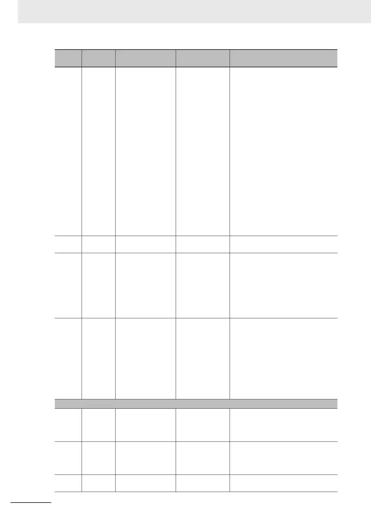
Item
No.
Parameter
No.
Item Range Description
6_24 X38
Latest Alarm Info.
Running Status 3
0000Hex to
FFFFHex
The running status 3 is displayed by a
four-digit hexadecimal.
0000 to FFFF hex
Bit15: ---
Bit14: OL (Overload warning)
Bit13: LOC (Light load detection)
Bit12: OL2 (Overload warning 2)
Bit11: OLP (During active drive)
Bit10: LIFE (Life warning)
Bit9: OHF (Fin Overheat warning)
Bit8: TRY (During retry)
Bit7: F
AN (Fan operation signal)
Bit6: REF (RUN command source)
Bit5: THM (Thermal warning)
Bit4: IPF (During restart after instantane-
ous power failure)
Bit3: SETM (2nd motor selection)
Bit2: IRDY (Operation ready)
Bit1: FDT1 (Over set frequency arrival
signal 1)
Bit0: FAR1 (Constant speed arrival)
6_25 X04
Latest Multiple Alarm
Sub Code 2
0 to 9999
The sub code when multiple alarms oc-
curred is displayed.
6_30 X108
Latest Alarm Info. Cu-
mulative Running
Time
0 to 655,350 hours
The cumulative time of the inverter RUN
state is displayed.
The cumulative operation time is dis-
played alternately in the upper digits and
lower digits.
When the lower three digits are dis-
played, an h (hours) is displayed in the
lowermost digit.
6_31 X49
Fault Counter
0 to 9999
1000 to 6553 [x10
LED]
The number of times the inverter trips is
displayed.
The number of times is saved in the EE-
PROM when the power is turned OFF.
Counting is performed from 0 to 65535,
and if 65535 times is exceeded, the dis-
play remains as 65535.
By setting “7: Clear alarm history” to Da-
ta Initialization (H03), the value is
cleared to 0.
2 The last alarm
6_00 X60
Last Info. Alarm Info.
Output Frequency
0.00 to 99.99,
100.0 to 590.0 [Hz]
The output frequency before slip com-
pensation is displayed in increments of
0.01 Hz. A value of 100.0 Hz or higher is
displayed in increments of 0.1 Hz.
6_01
X61
Last Alarm Info. Out-
put Current
0.00 to 99.99,
100.0 to 655.3 [A]
The output current is displayed. A cur-
rent value of 100.0A or higher is dis-
played in increments of 0.1 A.
Display unit: A (Ampere)
6_06 X65
Last Alarm Info. Run-
ning Status
0000Hex to
FFFFHex
The operation status is displayed by a
four-digit hexadecimal.
7 Other Functions
7-22
M1 Series Standard Type User's Manual (I669)

 Loading...


