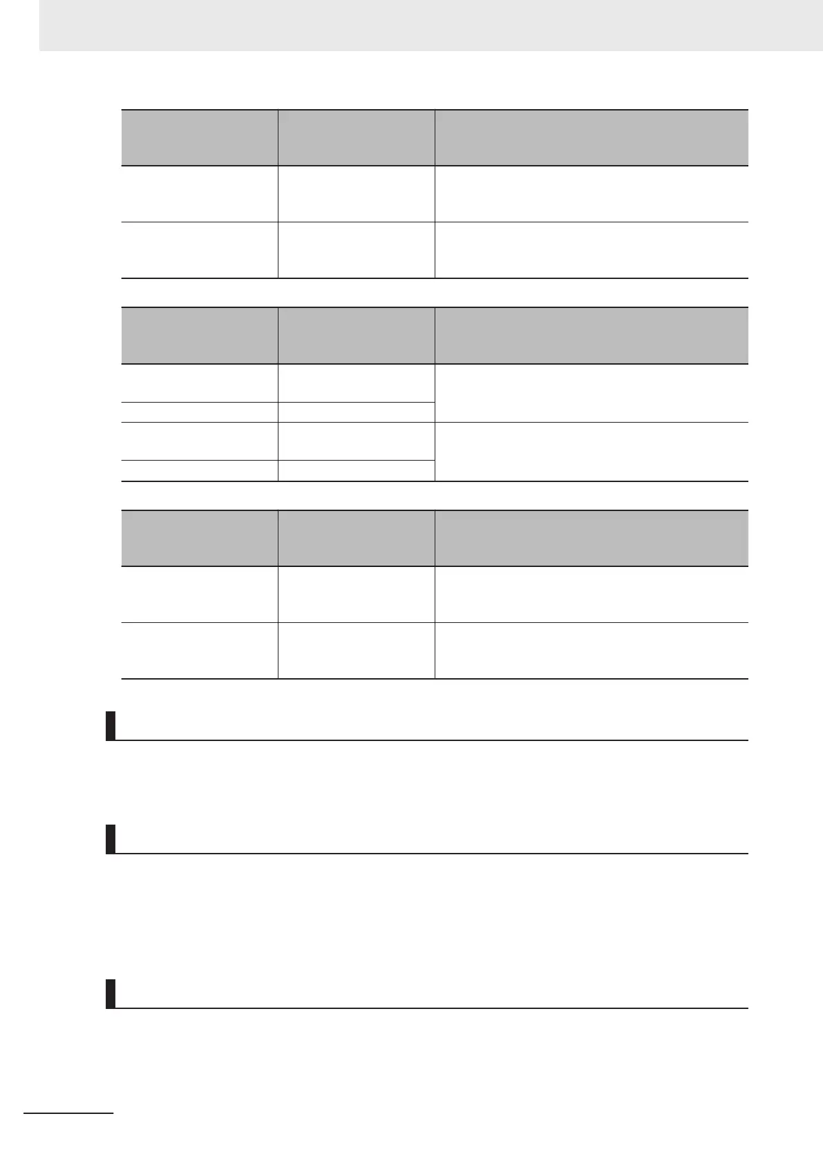
Input Terminal [AI1] Po-
larity Selection (C35) da-
ta
Function Description
0 Bipolar (-10 to 10 V)
When analog signals are changed to digital values af-
ter application of bias, values less than 0% are ena-
bled as minus values.
1 Unipolar (0 to 10 V)
When analog signals are changed to digital values af-
ter application of bias, values less than 0% are limited
at 0%.
Input Terminal [AI2] Op-
eration Selection (AII)
(C40) data
Function Description
0
4 to 20mA Unipolar (limit-
ed to less than 0)
When analog signals are changed to digital values af-
ter application of bias, values less than 0% are limited
at 0%.
1 0 to 20mA Unipolar
10
4 to 20mA Bipolar (nega-
tive number display)
When analog signals are changed to digital values af-
ter application of bias, values less than 0% are ena-
bled as minus values.
11 0 to 20mA Bipolar
Input Terminal [AI2] Po-
larity Selection (AIV)
(C45) data
Function Description
0 Bipolar (0 to 10 V)
When analog signals are changed to digital values af-
ter application of bias, values less than 0% are ena-
bled as minus values.
1 Unipolar (0 to 10 V)
When analog signals are changed to digital values af-
ter application of bias, values less than 0% are limited
at 0%.
Offsets (C31, C36, C41)
Set an offset with respect to the analog input voltage/current. It is also possible to correct the offset of
signals from external equipment.
Filter (C33, C38, C43)
Set the filter time constant with respect to the analog input voltage/current. As response slows down
when a large time constant is set, take the response speed of the equipment into consideration when
determining the time constant. When noise causes the input voltage to fluctuate, increase the time
constant.
Scaling of Analog Input Signal
The relationship between analog input signals and digital values for each individual analog input range
is as follows.
7 Other Functions
7-40
M1 Series Standard Type User's Manual (I669)

 Loading...


