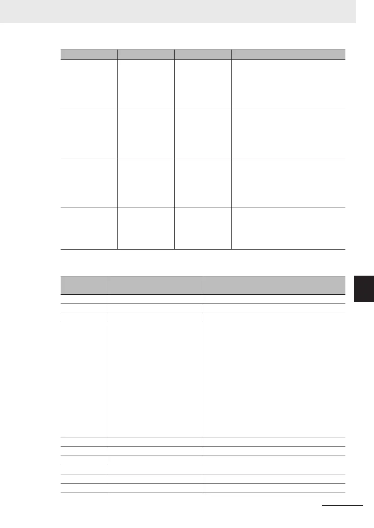
Analog input range Input signal Digital value (%) Gain/bias setting value
0 to 10V
0
10V
0%
100%
Gain reference value 100% (factory default
value)
Gain 100% (factory default value)
Bias reference value 100% (factory default
value)
Bias 0% (factory default value)
-10 to 10V
-10
0
+10V
-100%
0%
100%
Gain reference value 100% (factory default
value)
Gain 100% (factory default value)
Bias reference value 100% (factory default
value)
Bias 0% (factory default value)
0 to 20mA
0
20mA
0%
100%
Gain reference value 100% (factory default
value)
Gain 100% (factory default value)
Bias reference value 100% (factory default
value)
Bias 0% (factory default value)
4 to 20mA
4
20mA
0%
100%
Gain reference value 100% (factory default
value)
Gain 100% (factory default value)
Bias reference value 20%
Bias 0% (factory default value)
• Analog input signals 0% to 100% are converted at the following full scale, and used by the corre-
sponding functions.
E61, E62, E63
data
Description Full scale
0 Frequency command 0 to maximum output frequency [Hz]
1 Auxiliary frequency setting 1 Same as above (same as “0: Frequency reference”)
2 Auxiliary frequency setting 2 Same as above (same as “0: Frequency reference”)
3 PID command
Input Terminal [AI1] Analog Input Adjustment Minimum
Scale (C60) to Input T
erminal [AI1] Analog Input Ad-
justment Maximum Scale (C59) in the case of the ana-
log input terminal [AI1]
Input Terminal [AI2] Analog Input Adjustment Minimum
Scale (AII) (C66) to Input T
erminal [AI2] Analog Input
Adjustment Maximum Scale (AII) (C65) in the case of
the analog input terminal [AI2] (AII)
Input Terminal [AI2] Analog Input Adjustment Minimum
Scale (AIV) (C72) to Input Terminal [AI2] Analog Input
Adjustment Maximum Scale (AIV) (C71) in the case of
the analog input terminal [AI2] (AIV)
5 PID feedback Same as above (same as “3: PID command”)
6 Ratio setting 0 to 100%
7 Analog torque limiter 0 to 200%
9 Torque bias Same as above (same as “7: Analog torque limiter”)
10 Torque command 0 to 200%
11 Torque Current Command Same as above (same as “10: Torque command”)
7 Other Functions
7-41
M1 Series Standard Type User's Manual (I669)
7-3 Analog I/O Settings
7
7-3-2 Analog Input Adjustment Function
 Loading...


