E61, E62, E63
data
Description Full scale
17 Speed limit for forward rotation 0 to maximum output frequency [Hz]
18 Speed limit for reverse rotation
Same as above (same as “17: Speed limit for forward
rotation”)
20 Analog signal input monitor (Same as “3: PID command”)
21 PID feed forward (Same as “3: PID command”)
Gain/Bias
When setting gain and bias, take the maximum frequency required for your application to be 100%.
When setting the bias base point and gain base point data, take full scale of analog input (10 V or 20
mA) to be 100%.
Even if an analog input is unipolar, the frequency setting can be set as bipolar by setting bias as a
negative value. By setting C40 to 10 or 11 at terminal AI2(AII) and setting C45 to 1 at terminal
AI2(AIV), the frequency setting can be set as negative polarity by analog inputs of 0 points or less and
forward/reverse operation can be possible by only analog commands.
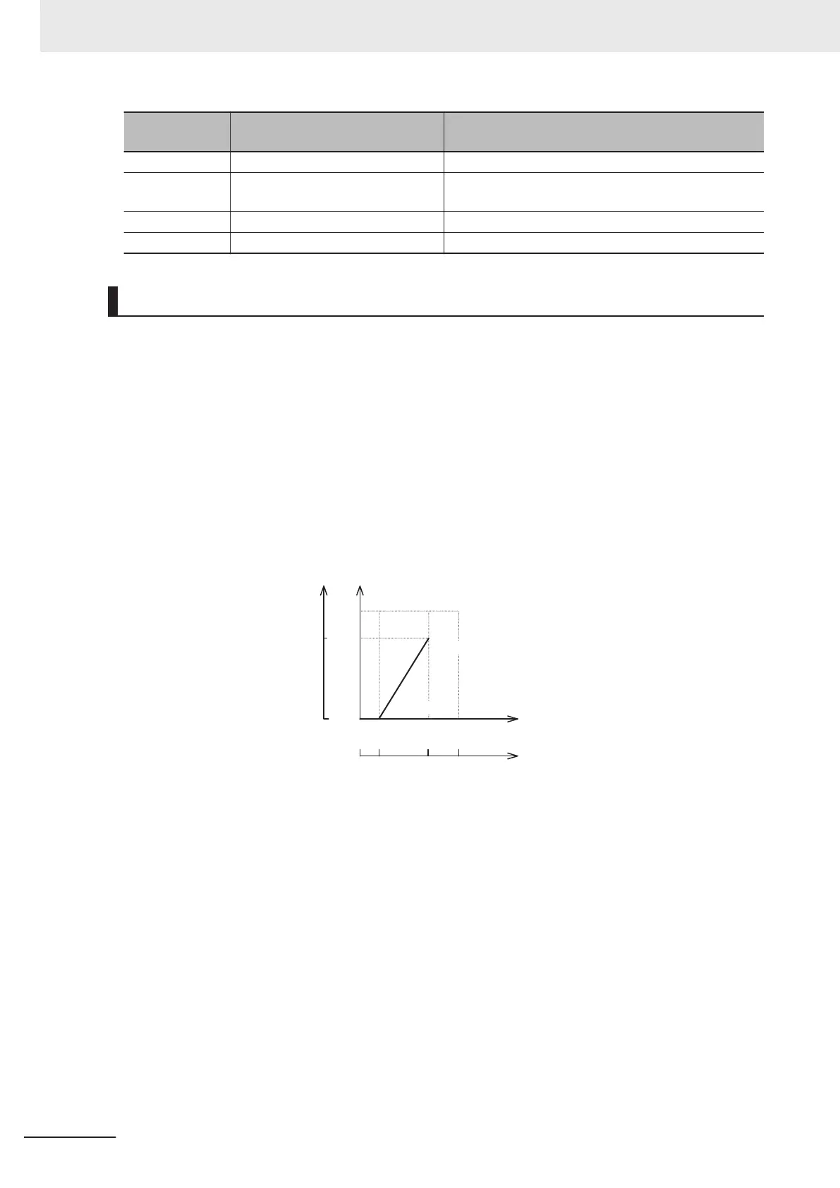
Example) When setting the set frequency 0 to 60 Hz by analog input AI1 1 to 5 V (1st Maximum Out-
put Frequency (F03) = 60 Hz)
Set frequency
Analog input (voltage)
Analog input (%)
(Analog input full scale:
Converted with 10 V taken as 100%)
(1st Maximum Output Frequency: Converted with F03 = 60 Hz taken as 100%)Hz %
60 Hz 100%
0
0 Hz
Input Terminal [AI1]
Gain(Command) (C32)
Input Terminal [AI1, AI2]
Bias for 1st Frequency
Command (F18)
100%50%10%
1 V 5 V 10 V
B point
A point
Input Terminal
[AI1, AI2]
Bias Analog
Input for
1st Frequency
Command (C50)
Input Terminal
[AI1] Gain
(Analog Input)
(C34)
(A point)
To take the frequency reference to be 0 Hz when the analog input is 1 V, set Input Terminal [AI1, AI2]
Bias for 1st Frequency Command (F18) to 0%. At this time, as 1 V becomes the bias base point and 1
V is equivalent to 10% of full scale 10 V of terminal AI1, set Input Terminal [AI1, AI2] Bias Analog Input
for 1st Frequency Command (C50) to 10%.
(B point)
T
o take the frequency reference to be the maximum frequency when the analog input is 5 V, set Input
Terminal [AI1] Gain (Command) (C32) to 100%. At this time, as 5 V becomes the gain base point and
5 V is equivalent to 50% of full scale 10 V of terminal AI1, set Input Terminal [AI1] Gain (Analog Input)
(C34) to 50%.
7 Other Functions
7-42
M1 Series Standard Type User's Manual (I669)
 Loading...


