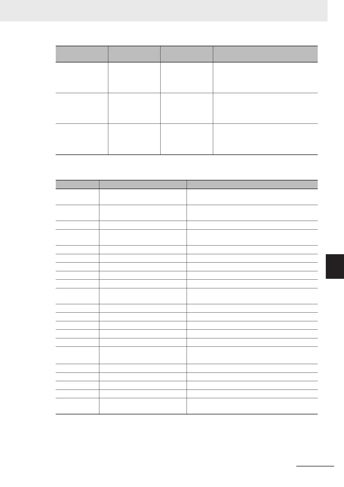
Analog output
range
Output signal Digital value (%) Gain/bias setting value
0 to 10V
0
10V
0%
100% (full scale val-
ue)
Gain reference value 100% (fixed)
Gain 100% (factory default value)
Bias reference value 0% (fixed)
Bias 0% (factory default value)
0 to 20mA
0
20mA
0%
100% (full scale val-
ue)
Gain reference value 100% (fixed)
Gain 100% (factory default value)
Bias reference value 0% (fixed)
Bias 0% (factory default value)
4 to 20mA
4
20mA
0%
100% (full scale val-
ue)
Gain reference value 100% (fixed)
Gain 100% (factory default value)
Bias reference value 0% (fixed)
Bias 0% (factory default value)
• The values of corresponding functions are converted to analog output 0% to 100% at the following
full scale and then output.
F31 data Description Full scale
0
Output frequency1 (before slip
compensation)
0 to maximum output frequency [Hz]
1
Output frequency2 (after slip com-
pensation)
Same as above
2 Output current 0 to inverter rated output current × 200%
3 Output voltage
0 to 250 V for the 200-V class
0 to 500 V for the 400-V class
4 Output torque 0 to rated motor torque × 200%
5 Load ratio 0 to rated motor load × 2
6 Power consumption 0 to standard applicable electric motor output × 200%
7 PID feedback 0 to 100%
8 Actual/Estimated speed 0 to maximum output frequency [Hz]
9 Main Circuit DC Voltage
0 to 500 V for the 200-V class
0 to 1,000 V for the 400-V class
10 Communication data AO 0 to 20,000
13 Motor output 0 to rated motor output × 200%
14 Calibration (+) Always full scale
15 PID command (SV) 0 to PID process command 100%
16 PID output (MV) 0 to maximum output frequency [Hz]
17
Position error in master-follower op-
eration (Bipolar)
*1
Monitor amount 0% to 50% to 100%
Position error -180 to 0 to 180°
18 Heatsink temperature 0 to 200℃
21 PG feedback value 0 to maximum output frequency [Hz]
27 Thermal load ratio 0 to 100% (OL1/OL2 trip level)
28 Internal Acc/Dec frequency 0 to maximum output frequency [Hz]
29
Output torque (Bipolar)
*1
Monitor amount 0% to 50% to 100%
Rated motor torque × -200% to 0% to 200%
*1. The output specifications of (signed) data are as described below.
7 Other Functions
7-47
M1 Series Standard Type User's Manual (I669)
7-3 Analog I/O Settings
7
7-3-5 Analog Output Function Selection

 Loading...


