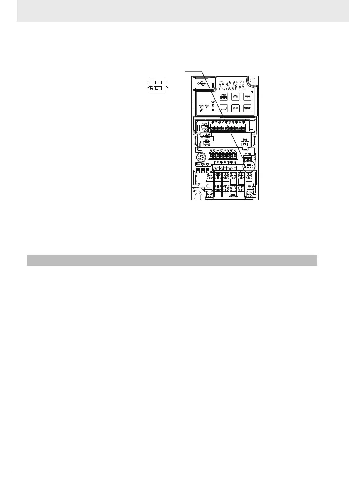
Set SW9 to enabled (OFF) or disabled (ON) so that both sides are at the same position at all times.
Safety function selector switch
ON
(Safety function
disabled)
OFF
Turn both OFF to use the safety function.
Turn both ON to not use the safety function.
When only one is ON, the logic of the SF1 and SF2 signals no longer matches and this causes an EN
circuit failure (alarm code: 39).
7-6-3
Wiring Safety Function for Use
The safety input function allows the inverter output when current flows in both the terminals [SF1] and
[SF2]. When the safety input function is activated, in compliance with the safety standards described
in 7-6-1 Overview of Safety Function on page 7-69, the output transistor operation of the inverter is
stopped safely (by shutting off its output). As a result, the motor stops with free run.
• It takes 50 ms or shorter from when the safety input is input till when the inverter shuts off the out-
put.
• En is displayed on the data display.
Perform wiring with reference to the wiring example to meet the applicable safety standards. Be sure
to use both the safety input [SF1] and [SF2] terminals and configure a system that turns OFF both of
the [SF1] and [SF2] terminals when the safety function is activated.
If the inverter detects that either the [SF1] or [SF2] terminal is OFF, the safety function is activated and
the inverter shuts off the output.
• The STO (Safe Torque Off) Performance Monitor (102: EDM) turns ON when the inverter detects
that both of the [SF1] and [SF2] terminal signals turn OFF and shuts off the output. If the EDM out-
put does not turn ON even when the inverter shuts off the output by the safety function, check the
[SF1] and [SF2] terminal input circuits and the EDM detection circuit.
• The EN circuit failure detected (101: DECF) turns ON when an error occurs in the circuit that detects
that the SF terminal is OFF.
7 Other Functions
7-70
M1 Series Standard Type User's Manual (I669)

 Loading...


