Parameter No. Function name Data
Default da-
ta
Unit
E20, E21, E27
Output Terminal [DO1]
Function Selection, Output
Terminal [DO2] Function
Selection, Output Terminal
[ROA, ROB] Function Se-
lection
101: DECF (EN circuit failure detect-
ed)
102: EDM (ST
O (Safe Torque Off)
Performance Monitor)
- -
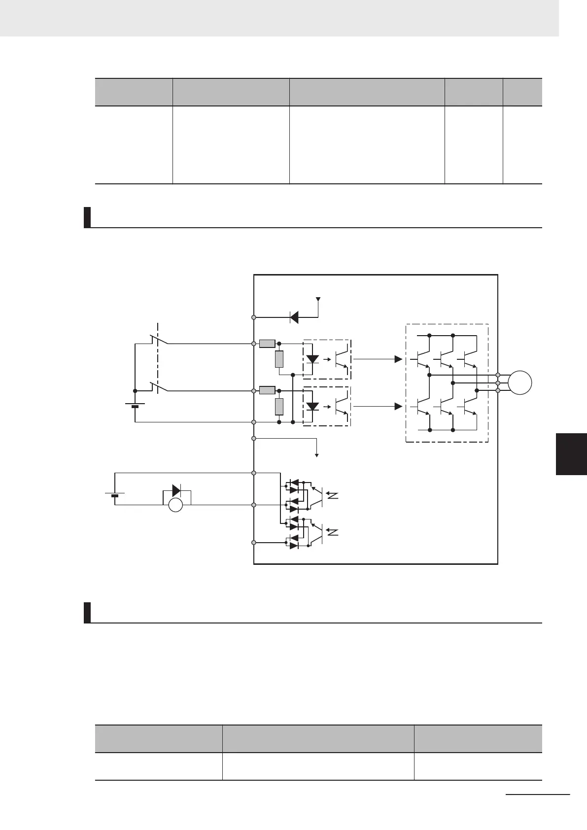
Wiring Example
Wiring example when EDM is enabled (for compliance with ISO13849-1 PL-e)
M
X
+24V
SF2
3G3M1
24V
SF1
DIC
DOC
DO1
o
r
DO2
EDM
System Configuration Example
To attain CAT.3, PLe/SIL3 as an overall system that uses the 3G3M1 Series, a PLe/SIL3 device must
at least be combined into the system.
Test pulse that is input to safety input terminals [SF1] and [SF2] from an external device must be 1 ms
or less.
The following shows an example of a safety interlock that is combined with the 3G3M1 Series.
Model
Applicable standard for system configura-
tion
Certification authority
G9SP
EN ISO13849-1 PL-e Cat4
(IEC61508 SIL3)
TÜV Rheinland
7 Other Functions
7-71
M1 Series Standard Type User's Manual (I669)
7-6 Safety Function
7
7-6-3 Wiring Safety Function for Use
 Loading...


