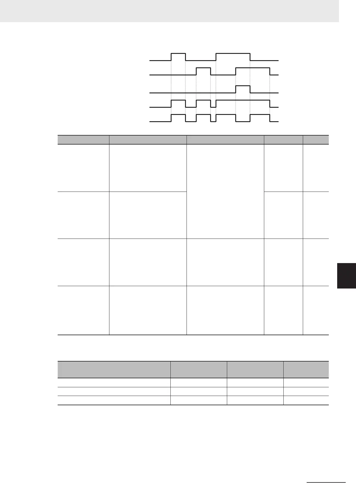
Logic output
signal selection 1
Logic output
signal selection 2
LOGx (AND)
LOGx (OR)
LOGx (XOR)
Parameter No. Function name Data Default data Unit
H315, H318, H321
Logical Expression 1 Opera-
tion Target 1
Logical Expression 2 Opera-
tion Target 1
Logical Expression 3 Opera-
tion T
arget 1
0 to 241: Same as the options
for E20, E21 and E27
(Except 206 to 208: LOG1 to
LOG3)
0 -
H316, H319, H322
Logical Expression 1 Opera-
tion Target 2
Logical Expression 2 Opera-
tion Target 2
Logical Expression 3 Opera-
tion T
arget 2
0 -
H317, H320, H323
Logical Expression 1 Logical
Operator
Logical Expression 2 Logical
Operator
Logical Expression 3 Logical
Operator
0: AND
1: OR
2: XOR
0 -
E20, E21, E27
Output Terminal [DO1] Func-
tion Selection, Output T
ermi-
nal [DO2] Function Selection,
Output T
erminal [ROA, ROB]
Function Selection
206: LOG1 (Logic operation
output 1)
0 -
207: LOG2 (Logic operation
output 2)
208: LOG3 (Logic operation
output 3)
Each logic operation output signal requires different parameter settings.
Set the necessary parameters according to the table below.
Selected signal
Logic output signal
selection 1
Logic output signal
selection 2
Operator selec-
tion
206: Logic operation output 1 (LOG1) H315 H316 H317
207: Logic operation output 2 (LOG2) H318 H319 H320
208: Logic operation output 3 (LOG3) H321 H322 H323
(Example) To output the result of the AND operation between Run Signal (0: RUN) and Over set frequency
arrival signal 1 (2: FDT1) to the multifunction output terminal DO2 as a Logic operation output 1
(LOG1).
Output Terminal [DO2] Function Selection (E21): 206 (LOG1)
Logical Expression 1 Operation Target 1 (H315): 0 (RUN)
Logical Expression 1 Operation Target 2 (H316): 2 (FDT1)
Logical Expression 1 Logical Operator (H317): 0 (AND)
7 Other Functions
7-95
M1 Series Standard Type User's Manual (I669)
7-8 Functions Related to Protection, Warning and Various Output Signals
7
7-8-9 Logic Operation Output Signal (LOG1 to LOG3)

 Loading...


