Parameter No. Function name Data
Default
data
Unit
E20, E21, E27
Output Terminal [DO1] Function
Selection, Output Terminal [DO2]
Function Selection, Output Termi-
nal [ROA, ROB] Function Selec-
tion
84: MNT (Maintenance timer
counted up)
-
-
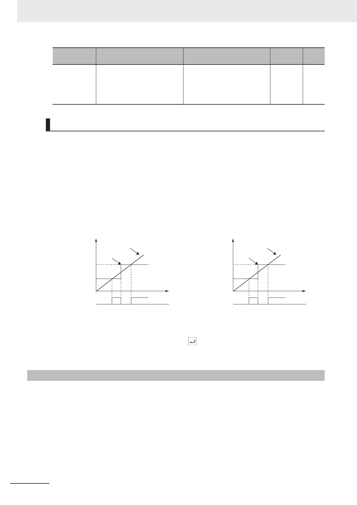
Maintenance timer counted up (E20, E21, E27 = 84: MNT)
To output this signal, allocate “84: MNT (Maintenance timer counted up)” to Output Terminal [DO1]
Function Selection (E20), Output Terminal [DO2] Function Selection (E21) and Output Terminal [ROA,
ROB] Function Selection (E27).
The signal is output when 1st Startup Count for Motor (H44) reaches the value set at 1st Preset Start-
up Count for Motor Maintenance (H79), or 1st Cumulative Motor Run Time (H94) reaches the value
set at 1st Motor Maintenance Interval (H78).
This function is exclusively for the 1st control. The maintenance timer signal is not output even if 2nd
Cumulative Motor Run T
ime (A51)/2nd Startup Counter for Motor (A52) exceeds the set time period or
set number of times.
<For half-yearly maintenance>
Time
1st Cumulative Motor Run Time (H94)
H78 = 876
(8760 hours = 1 year)
H78 = 438
(4380 hours = 6 months)
Maintenance timer
“MNT”
ON
ON
H94
H78
<For maintenance performed every 1,000 times>
Time
1st Startup Count for Motor (H44)
H79 = 07D0
(2,000 times)
H79 = 03E8
(1,000 times)
Maintenance timer
“MNT”
ON
ON
H44
H79
When the maintenance time is reached, or when the set number of startups for maintenance is
reached, again set a numeric value at 1st Motor Maintenance Interval (H78) or 1st Preset Startup
Count for Motor Maintenance (H79), and press the key to reset the output signal, and restart the
measurement of the time period or the number of startups.
7-8-9
Logic Operation Output Signal (LOG1 to LOG3)
Logical operations (AND, OR, XOR) are performed on signals that can be allocated to output terminals
[DO1], [DO2] and [ROA, ROB], and the result can be output from output terminals. Set “206: LOG1
(Logic operation output 1),” “207: LOG2 (Logic operation output 2),” or “208: LOG3 (Logic operation
output 3)” at Output Terminal [DO1] Function Selection (E20), Output Terminal [DO2] Function Selec-
tion (E21) and Output Terminal [ROA, ROB] Function Selection (E27). However, “206: LOG1 (Logic
operation output 1)” to “208: LOG3 (Logic operation output 3)” cannot be selected for the operation
target data.
7 Other Functions
7-94
M1 Series Standard Type User's Manual (I669)

 Loading...


