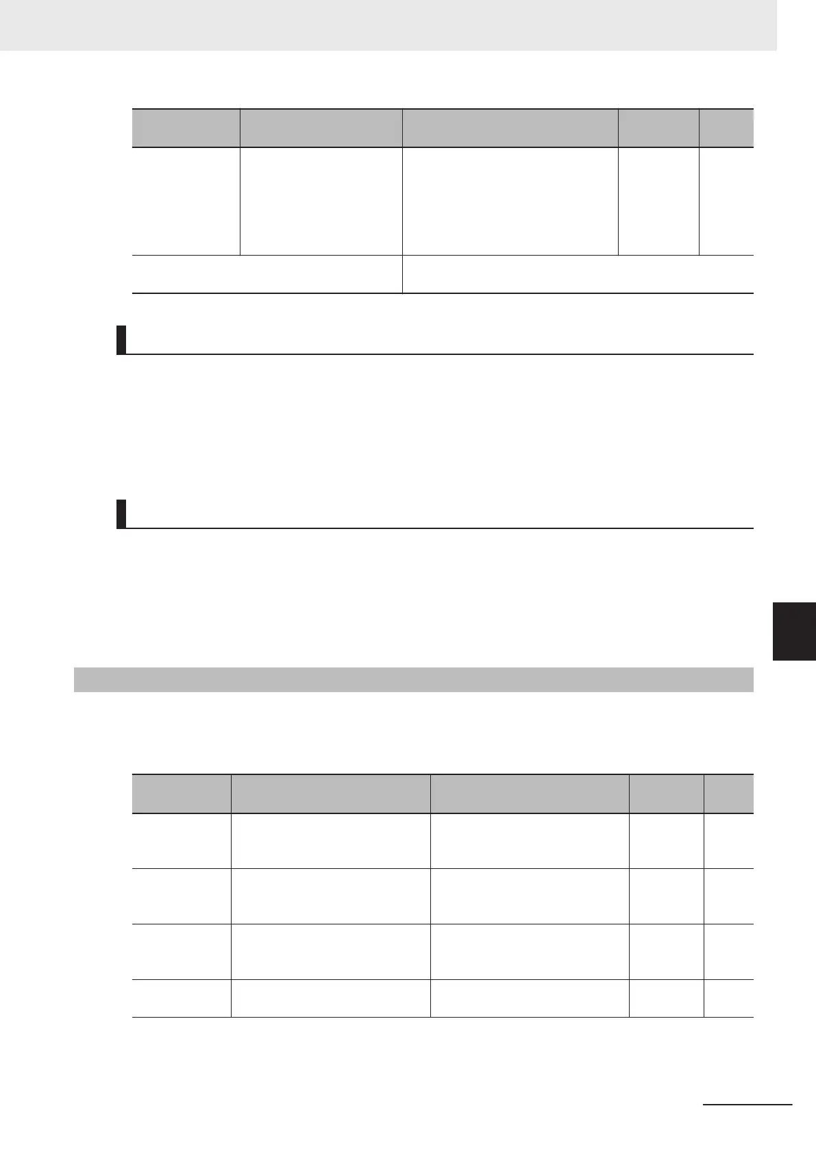
Parameter No. Function name Data
Default da-
ta
Unit
E20, E21, E27
Output Terminal [DO1]
Function Selection, Output
Terminal [DO2] Function
Selection, Output Terminal
[ROA, ROB] Function Se-
lection
237: RNT (RUN time over)
236: ONT (Power ON time over)
- -
Related function
Cumulative Operation T
ime (M20), Total RUN Time Monitor
(W179)
Power ON Time Over (236: ONT)
• To output this signal, allocate “236: ONT” to Output Terminal [DO1] Function Selection (E20), Output
Terminal [DO2] Function Selection (E21) or Output Terminal [ROA, ROB] Function Selection (E27).
•
The power ON time of the inverter's main circuit is counted and output to Cumulative Operation
Time (M20). When RUN Time Over (RNT)/Power ON Time Over (ONT) Detection Level (E154)
elapses, the ONT terminal (236: Power ON time over) turns ON.
RUN time over (238: RNT)
• To output this signal, allocate “238: RNT” to Output Terminal [DO1] Function Selection (E20), Output
Terminal [DO2] Function Selection (E21) or Output Terminal [ROA, ROB] Function Selection (E27).
•
Time is measured during inverter operation (inverter output signal (35: RUN2) is ON) and the result
is output to Total RUN Time Monitor (W179). When RUN Time Over (RNT)/Power ON Time Over
(ONT) Detection Level (E154) elapses, RNT terminal (238: RUN time over) turns ON.
7-8-8
Maintenance monitor
The Maintenance timer counted up (MNT) signal is output when the cumulative operation time for mo-
tor 1 exceeds the preset time, or when the number of startups for motor 1 exceeds the preset number
of times.
Parameter No. Function name Data
Default
data
Unit
H78 1st Motor Maintenance Interval
0: Disable
1 to 9999: Maintenance interval
(in 10 hours)
8760 Time
H94/A51
1st Cumulative Motor Run
Time/2nd Cumulative Motor Run
Time
0 to 9999 (Counted automatically
as the operation time elapses)
0
Time
H79
1st Preset Startup Count for Mo-
tor Maintenance
0: Disable
1 to 65535: Preset startup count
for maintenance
0 Times
H44/A52
1st Startup Count for Motor/2nd
Startup Counter for Motor
0 to 65535 (Counted automatical-
ly during startup)
0 Times
7 Other Functions
7-93
M1 Series Standard Type User's Manual (I669)
7-8 Functions Related to Protection, Warning and Various Output Signals
7
7-8-8 Maintenance monitor

 Loading...


