Name Output signal
E20, E21, E27 al-
located data
Operation level
Frequency arrival
detection width
Range: 0.0 to 500.0
Hz
Range: 0.0 to 10.0
Hz
Set-frequency-only ar-
rival signal
FDT3 183 E31 E30
Set-frequency-only ar-
rival signal 2
FDT4 185 E36 E30
E31/E36
E30
E30
ON ON
E31/E36
E30
E30
Set-frequency-only arrival signal “FDT3”
Set-frequency-only arrival signal 2 “FDT4”
Output frequency
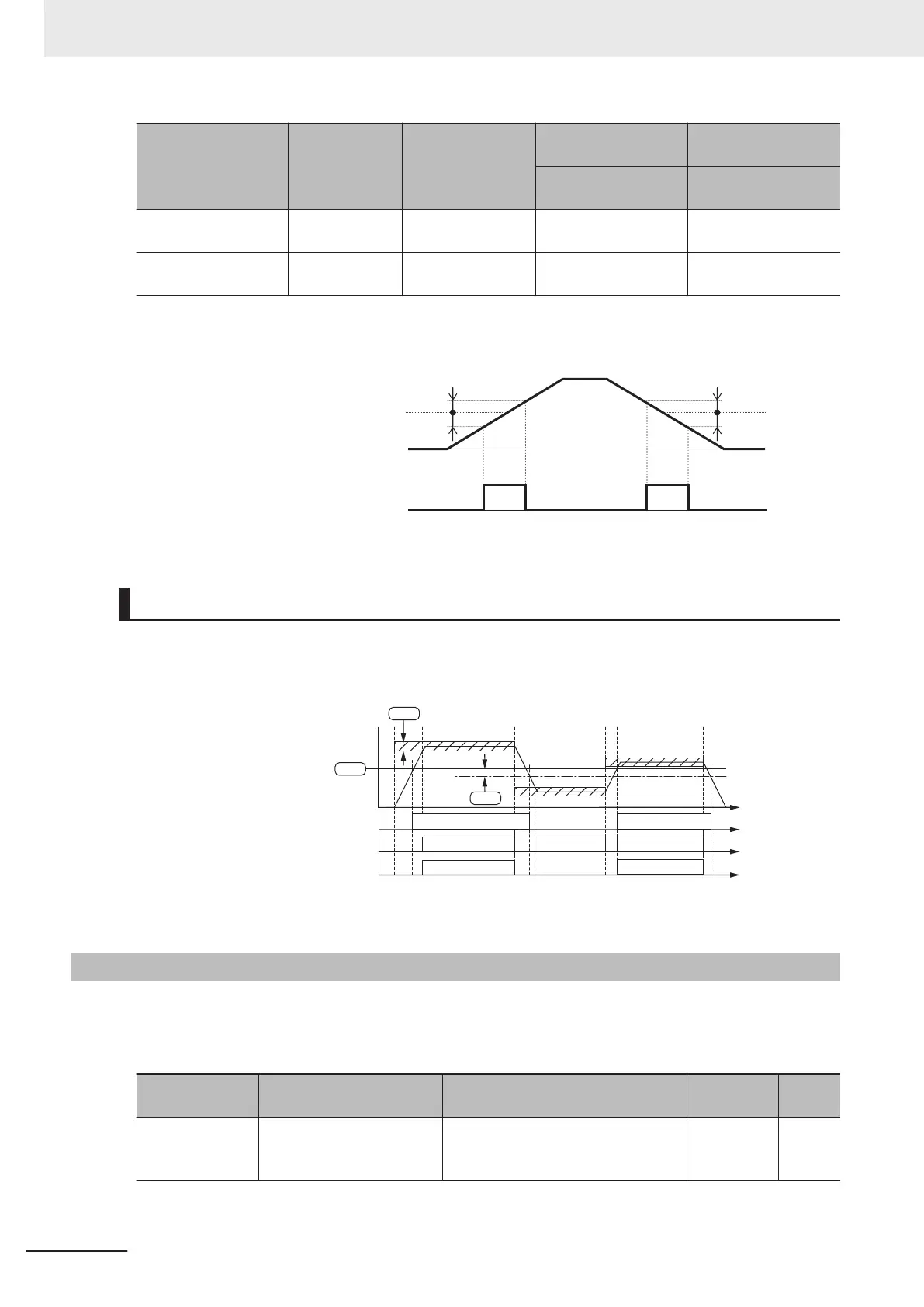
Frequency Match Detection (E20, E21, E27 = 87: FAR1FDT1)
This is an AND composite signal of FAR1 and FDT1, which turns ON when both the conditions are
established.
ONO
N
ON
ON
0
Over set frequency arrival signal 1 “FDT1”
Frequency arrival signal 1 (constant speed) “FAR1”
Frequency match detection “FAR1FDT1”
Output frequency
ON
ON
t
t
t
t
ON
E32
E31
E32
7-8-7
Power ON Time Over/RUN Time (ONT/RNT)
• If the total RUN time and power ON time of the inverter main circuit exceeds the time set at RUN
Time Over (RNT)/Power ON Time Over (ONT) Detection Level (E154), the inverter will output the
RUN time over/Power ON time over (RNT/ONT) signal.
Parameter No. Function name Data
Default da-
ta
Unit
E154
RUN Time Over (RNT)/
Power ON Time Over
(ONT) Detection Level
0: Function disabled
1 to 9999 [x10h] (10 to 99.990 hours)
0 10 hex
7 Other Functions
7-92
M1 Series Standard Type User's Manual (I669)

 Loading...


