Additional Information
When using this signal for disconnection detection, set the disconnection detection level to Ana-
log Input [AI1] Detection Upper Limit Level (E157)/Analog Input [AI2] Detection Upper Limit Lev-
el (E160).
(During normal operation, range exceeding the upper limit value is used. If the range falls below
the lower limit value, a disconnection will be detected.)
7-8-20
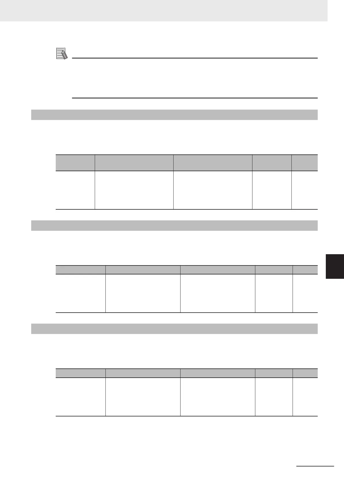
Frequency Reference Selection Status Signal (FREF)
This signal is output when the frequency reference is set to Operator (Frequency Reference Selection
(F01/C30) = 0, 8), or when the forced operator function (35: OPE terminal) is allocated.
The signal is OFF when the frequency reference is input via other than the Digital Operator
.
Parameter
No.
Function name Data Default data Unit
E20, E21, E27
Output Terminal [DO1] Function
Selection, Output Terminal
[DO2] Function Selection, Out-
put Terminal [ROA, ROB] Func-
tion Selection
188: FREF (Frequency Com-
mand Source)
- -
7-8-21
RUN Command Status Signal (REF)
This signal is output when the RUN command selection is set to Operator (RUN Command Selection
(F02/E102) = 0, 2, 3), or when the forced operator function (35: OPE) is allocated.
The signal is OFF when the RUN command selection is set to other than the Operator.
Parameter No. Function name Data Default data Unit
E20, E21, E27
Output Terminal [DO1] Func-
tion Selection, Output Termi-
nal [DO2] Function Selection,
Output Terminal [ROA, ROB]
Function Selection
8: REF (RUN command
Source)
- -
7-8-22
2nd control under selection signal (SETM, SWM1)
The SETM signal is output when the SET terminal (12: Set 2nd control) of multifunction input is ON
and the 2nd control has been selected. If the SET terminal is OFF and the 1st control has been select-
ed, the SWM1 signal is output.
Parameter No. Function name Data Default data Unit
E20, E21, E27
Output Terminal [DO1] Func-
tion Selection, Output Termi-
nal [DO2] Function Selection,
Output Terminal [ROA, ROB]
Function Selection
48: SWM1 (1st motor in oper-
ation)
49: SETM (2nd motor in oper-
ation)
- -
7 Other Functions
7-105
M1 Series Standard Type User's Manual (I669)
7-8 Functions Related to Protection, Warning and Various Output Signals
7
7-8-20 Frequency Reference Selection Status Signal (FREF)

 Loading...


