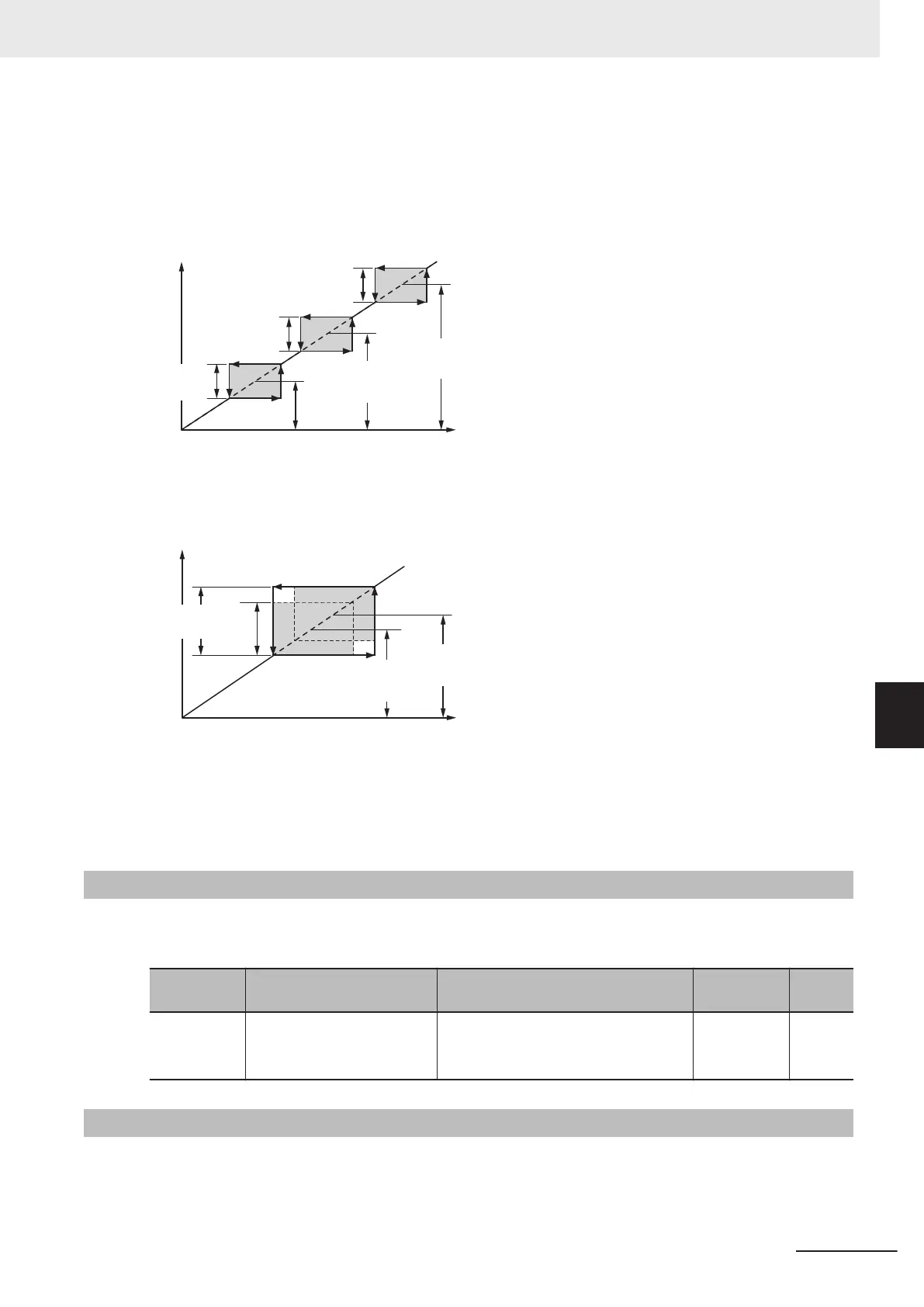
• When the set frequency is increased and the set frequency enters the jump frequency band, the in-
ternal set frequency is kept constant at the lower limit of the jump frequency band. If the set frequen-
cy exceeds the upper limit of the jump frequency band, the internal set frequency reaches the value
of the set frequency. When the set frequency is reduced, the opposite relationship to that during in-
crease is realized.
Internal set frequency
Set frequency
Jump
Frequency Skip
Width (C04)
Jump
Frequency Skip
Width (C04)
Jump
Frequency Skip
Width (C04)
Jump
Frequency 3
(C03)
Jump
Frequency 2
(C02)
Jump
Frequency 1
(C01)
• If two or more jump frequency ranges overlap each other, the lower limit value and the upper limit
value of the overlapped jump frequency become the lower limit and upper limit frequencies of the
actual jump frequency range.
Set frequency
Jump
Frequency 2
(C02)
Jump
Frequency 1
(C01)
Jump
Frequency
Skip Width
(C04)
Internal set frequency
Actual jump
frequency
width
During acceleration and deceleration, the output frequency changes continuously in accordance with
the acceleration/deceleration time.
Although the jump frequency can be set at three locations, the jump frequency width is common at the
three locations.
7-9-6
RUN Direction Limit Selection
This function limits the rotation direction of the motor output.
It can be activated either via the control circuit terminal block or the Digital Operator.
Parameter
No.
Function name Data Default data Unit
H08
Reverse Rotation Prevention
Function
0: Disable
0 -1: Enable (Reverse rotation inhibited)
2: Enable (Forward rotation inhibited)
7-9-7
Permission of RUN Command
The RUN command is not accepted while the Permission of Run command is OFF.
7 Other Functions
7-117
M1 Series Standard Type User's Manual (I669)
7-9 Other Operation Functions
7
7-9-6 RUN Direction Limit Selection

 Loading...


