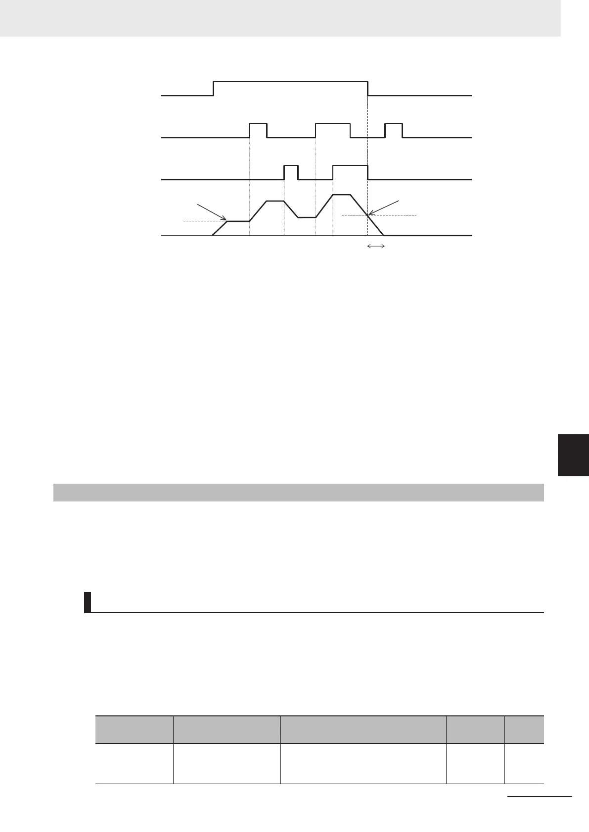
RUN command
Frequency reference when the next
RUN command is ON when H61 = 1
Frequency reference when the previous
RUN command is OFF when H61 = 1
Operate in accordance with Stop Selection (H11)
UP input
DWN input
Output frequency
• The frequency reference operates in accordance with the acceleration/deceleration time and accel-
eration/deceleration pattern (refer to 5-6-2 Acceleration/Deceleration Pattern on page 5-40) that is
adopted during operation.
• When the UDC terminal turns ON, the frequency reference is set to 0 Hz and a deceleration stop is
performed. The UDC terminal is enabled and the frequency reference becomes 0 Hz also when the
UP terminal or DWN terminal is ON. When the UDC terminal is turned OFF during a deceleration
stop, the frequency reference is operated from 0 Hz in accordance with the UP terminal or DN termi-
nal.
Note) When 0: Other than linear acceleration/deceleration, 1: S-curve acceleration/deceleration, 2: S-
curve acceleration/deceleration (Arbitrary) and 3: Curve acceleration/deceleration is selected at Accel-
eration/Deceleration Pattern Selection (H07), the output frequency changes for a while even if the
“UP” terminal and “DWN” terminal are turned OFF
.
7-9-11
AVR (Automatic Voltage Regulator) Function
This is a function for automatically correcting the output voltage to the motor even if the inverter in-
coming voltage fluctuates.
This function is used to avoid a drop in the output torque of the motor or the overexcitation state.
Note, however
, that the inverter cannot output voltage exceeding the incoming voltage to the inverter.
AVR (Automatic Voltage Regulator) Function Setting
The AVR (automatic voltage regulator) function is set to enabled or disabled by 1st AVR Function Se-
lection (E122)/2nd AVR Function Selection (E123).
• The voltage output in the motor is based on the voltage selected at 1st Rated Voltage at Base Fre-
quency (F05)/2nd Rated V
oltage at Base Frequency (A03).
Note, however, that the inverter cannot output voltage exceeding the incoming voltage to the inver-
ter.
Parameter No. Function name Data
Default da-
ta
Unit
E122/E123
1st AVR Function Selec-
tion/2nd AVR Function
Selection
0: Disable
1: Enable
1 -
7 Other Functions
7-121
M1 Series Standard Type User's Manual (I669)
7-9 Other Operation Functions
7
7-9-11 AVR (Automatic Voltage Regulator) Function

 Loading...


