Input terminal Input range
Bias Gain Polarity se-
lection
(Range se-
lection)
Filter Offset
Bias
Base
point
Gain
Base
point
AI1
0 to 10 V
-10 to 10 V
C55 C56 C32 C34 C35 C33 C31
AI2 (AII func-
tion)
4 to 20 mA,
0 to 20 mA
C61 C62 C37 C39 C40 C38 C36
AI2 (AIV func-
tion)
0 to +10 V C67 C68 C42 C44 C45 C43 C41
The following processing is performed during polarity selection C35, C45 and range selection C40.
C35: Set the input range of the AI1 terminal.
C35 Terminal input specifications
0 -10 to 10 V
1 0 to 10 V (A negative voltage is considered as 0 V.)
C40: Set the input range of the AI2 (AII function) terminal.
C40 Terminal input specifications
Handling when the bias value is set as a negative
value
0 4 to 20 mA
0 is set as the limit for a value below 0.
1 0 to 20 mA
10 4 to 20 mA
A value below 0 is enabled as a negative value.
11 0 to 20 mA
C35: Set the input range of the AI2 (AIV function) terminal.
C35 Terminal input specifications
Handling when the bias value is set as a negative
value
0 0 to +10 V A value below 0 is enabled as a negative value.
1 0 to +10 V 0 is set as the limit for a value below 0.
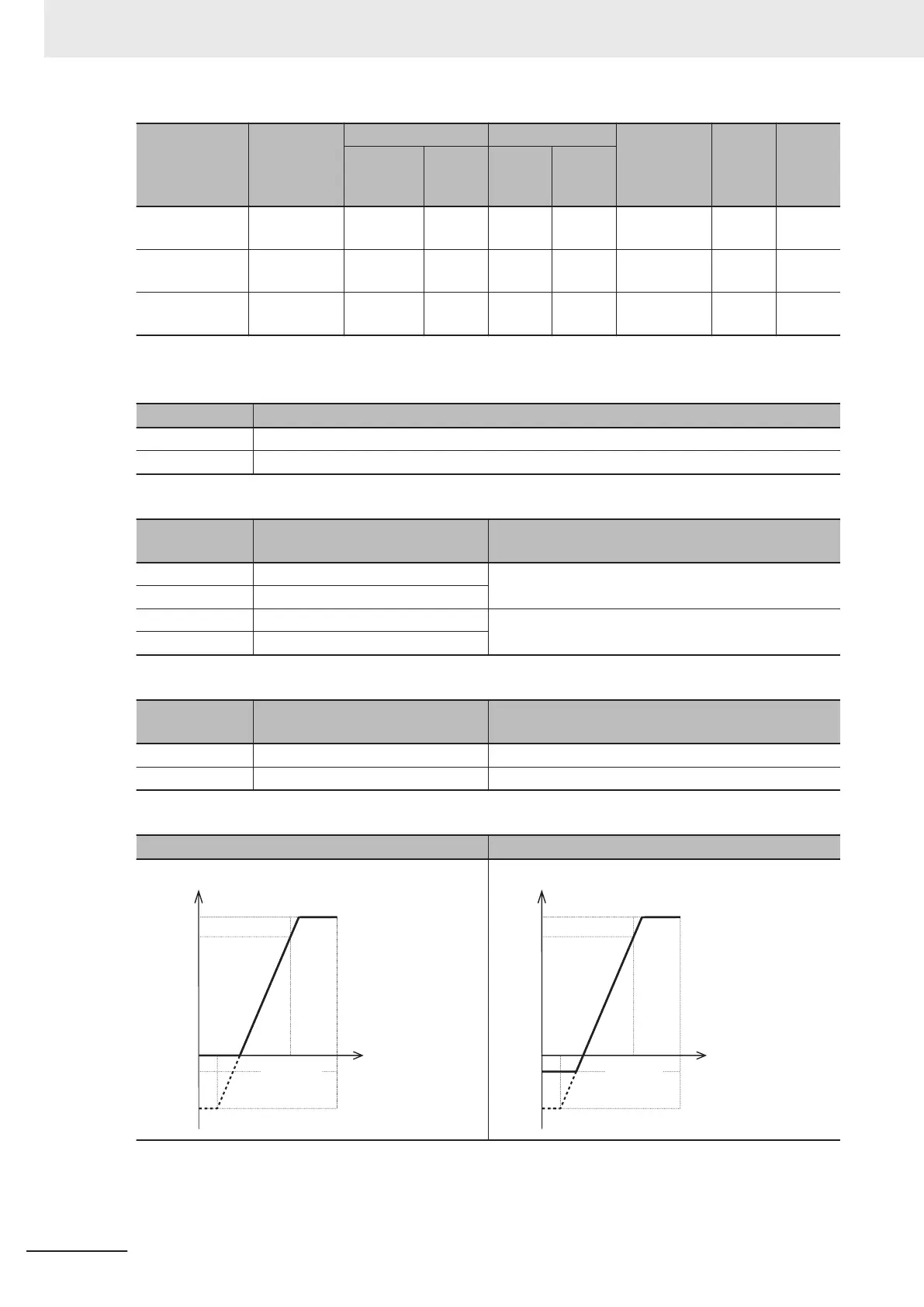
An example of PID process control is shown below.
Used for unipolar Used for bipolar
100%
Gain
Bias
0%
-10%
Bias
base point
Gain
base point
100%
Analog
input
A point
B point
The value after conve
rsion becomes 0% to 100% or more.
The value after conversion becomes -100% to 100% or more.
100%
Gain
Bias
0%
-10%
Bias
base point
Gain
base
point
100%
Analog
input
A point
B point
An example of dancer control is shown below.
7 Other Functions
7-130
M1 Series Standard Type User's Manual (I669)
 Loading...


