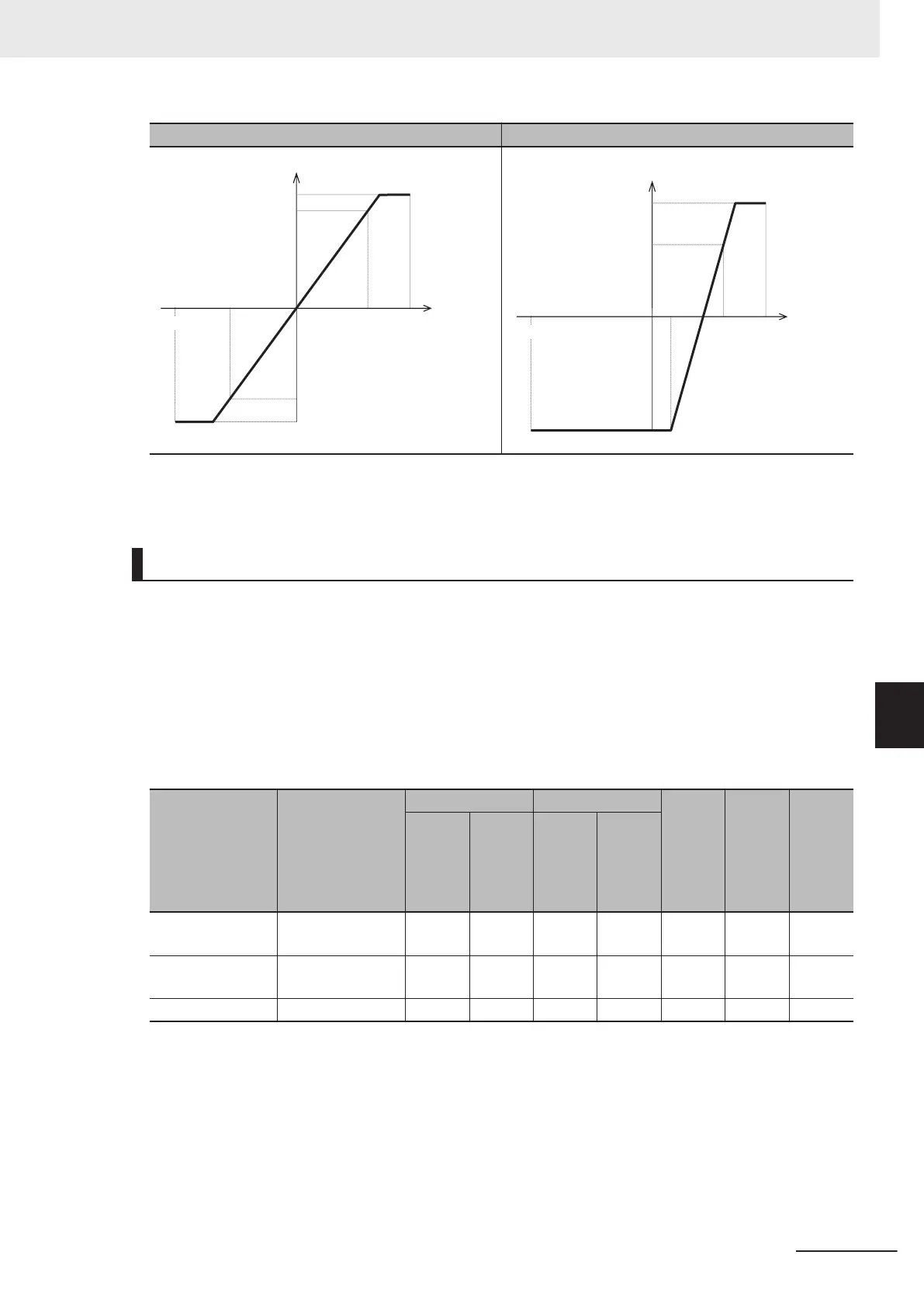
Bias = 0%, Bias base point = 0% Bias ≠ 0%, Bias base point ≠ 0%
PID process command
100%
Gain
0%
B point
100%
Analog
input
Gain
base point
-100%
-100%
PID process command
100%
Gain
Bias
0
%
B point
A point
100%
Analog
input
Bias base
point
-100%
Gain
base point
• PID command by communication (J02 = 4)
Communication parameter (S13): T
ransmission data 20000d/100% PID command.
PID Control Feedback Selection (E119)
• E119 = 0: Analog input terminal
If 0: Analog input terminal ([AI1], [AI2] AII function, [AI2] AIV function) is selected for PID Control
Feedback Selection (E1
19), allocate “5: PID feedback value” to the terminal used in feedback input
by any one of E61, E62 or E63. The analog input value is internally controlled as 0% to 100%. For
details on analog input, refer to 7-3-1
Analog Input Function Selection on page
7-35.
When analog input is applied to PID feedback, the following gains, biases, filters and offsets are appli-
cable.
Input terminal Input range
Bias Gain Polari-
ty se-
lection
(Range
selec-
tion)
Filter Offset
Bias
Base
point
Gain
Base
point
AI1
0 to 10 V, -10 to
10 V
C55 C56 C32 C34 C35 C33 C31
AI2 (AII function)
4 to 20 mA, 0 to
20 mA
C61 C62 C37 C39 C40 C38 C36
AI2 (AIV function) 0 to +10 V C67 C68 C42 C44 C45 C43 C41
• E119 = 2: Modbus communication
If “2: Modbus communication” is set to PID Control Feedback Selection (E119), set a value in com-
munication parameter (S30) under the assumption of 20000d = 100%.
• E1
19 = 3: Pulse train frequency
If “03: Pulse train frequency” is set to PID Control Feedback Selection (E119), the inverter captures
a value converted into a percentage with the maximum frequency as 100% where the correction fac-
tor (d63/d62) is multiplied with the frequency value [kP/s] of the captured pulse train input.
7 Other Functions
7-131
M1 Series Standard Type User's Manual (I669)
7-9 Other Operation Functions
7
7-9-13 PID Function
 Loading...


