f* [Hz] = Np [kp/S] ×
Input Terminal [PIA][PIB] Pulse Scaling Factor Numerator (d17)
Input Terminal [PIA][PIB] Pulse Scaling Factor Denominator (d16)
PV [%] = f* [Hz] ×
100
Maximum frequency [Hz]
PV [%]: PID feedback input
f* [Hz]: Frequency set value
Np [kp/s]: Entered input pulse frequency
Feedforward Selection
Feedforward is applied during PID process control. Select at PID Control PID Feedforward Selection
for Process Control (E121). If “1: Analog input terminal” is selected, allocate “21: PID feed forward val-
ue” to either of Input Terminal [AI1] Function Selection (E61), Input Terminal [AI2] Function Selection
(AII) (E62) or Input Terminal [AI2] Function Selection (AIV) (E63). If not allocated, feedforward control
is not performed.
Feedforward is disabled during dancer control.
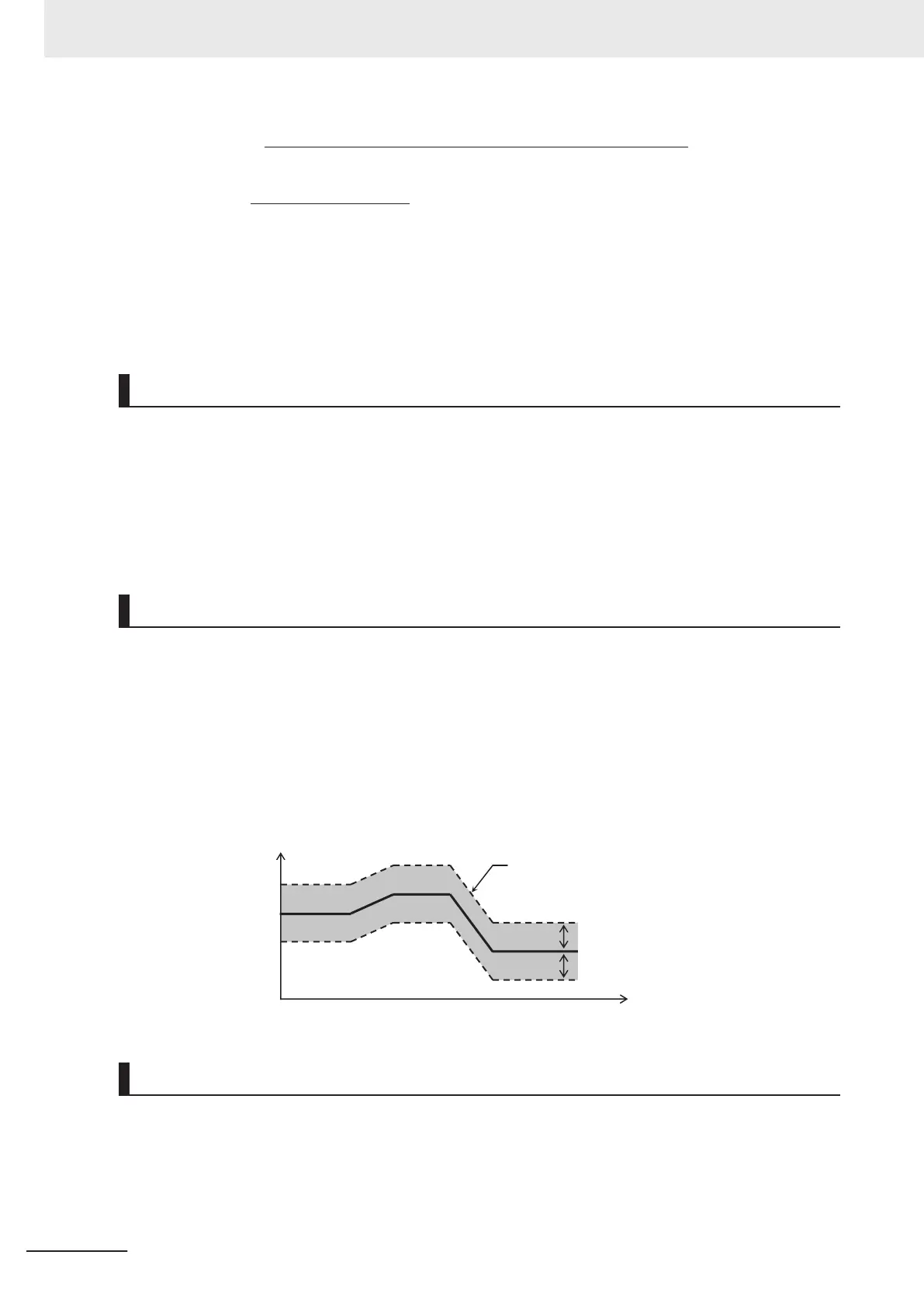
PID Variable Range
In the case of PID process control, the PID output is restricted to a variable range with reference to the
target value.
When using this function, set PID Control PID Output Variable Range for Process Control (E120).
Then, the output frequency will be limited to within a range of Target value ± (E120) with the maximum
frequency as 100%.
If E120 is 0.0, the function is disabled. The function is also disabled when “4: Process normal opera-
tion, opposite operation available” or “5: Process inverse operation, opposite operation available” is
set to PID Control Function Selection (J01).
PID output [%]
PID output range
PID Control PID Output Variable
Range for Process Control (E120)
PID Control PID Output Variable
Range for Process Control (E120)
PID target value
Time [s]
PID Reverse Output
If the PID calculation results are negative during regular PID control (J01 = 1, 2), the frequency refer-
ence to the inverter is limited at 0 Hz. If PID Control Function Selection (J01) is set to “4: Process nor-
mal operation, opposite operation available” or “5: Process inverse operation, opposite operation avail-
able,” an inverse output can be performed for the inverter if the PID calculation results are negative.
7 Other Functions
7-132
M1 Series Standard Type User's Manual (I669)
 Loading...


