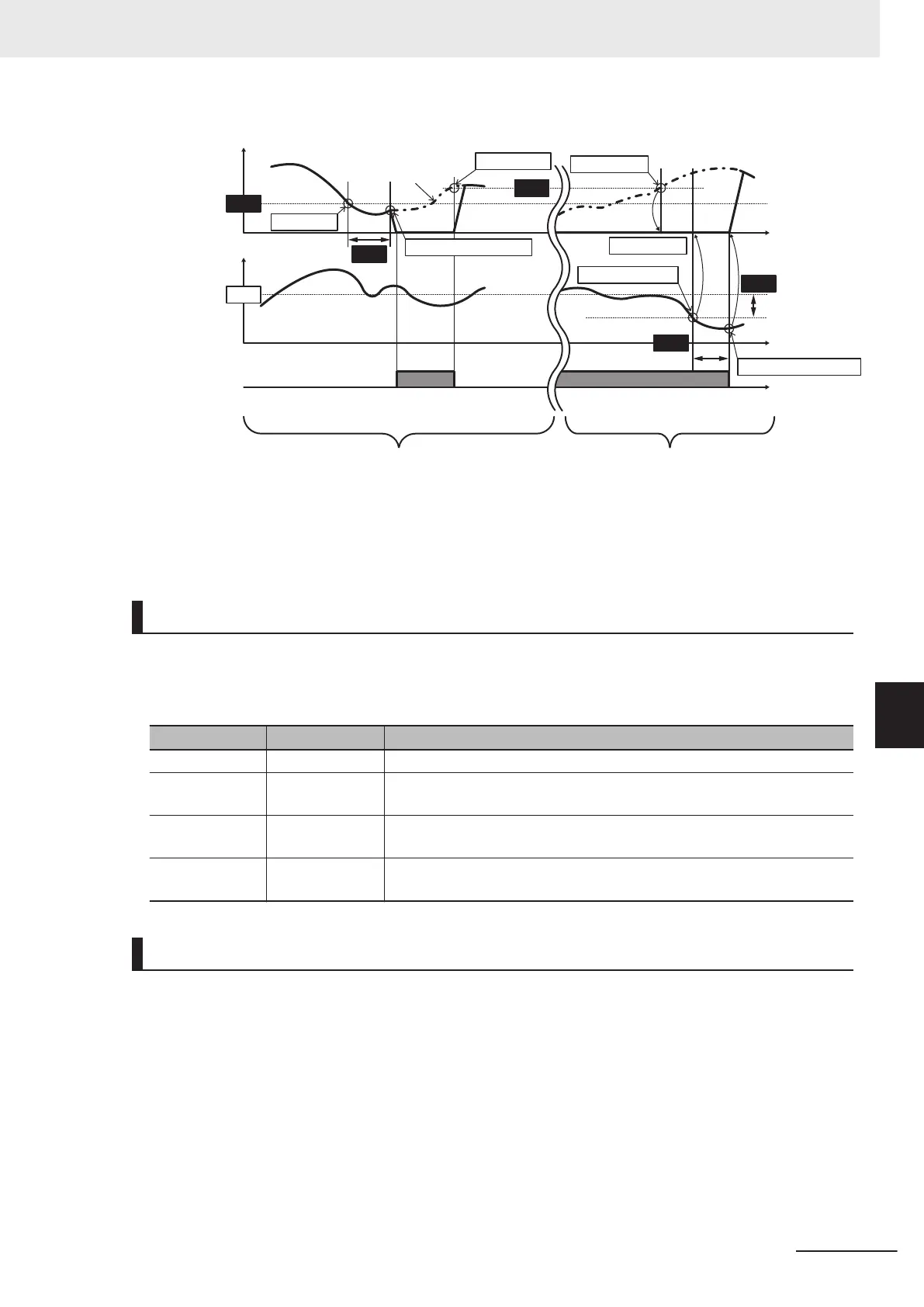
[J23 = 0] & [J24 = 0]
(Factory default value) (Factory default value)
[J23 ≠ 0] & [J24 ≠ 0]
Wakeup signal
“PID-STP”
Feedback PV(%)
Output frequency (Hz)
ON
ON
t
t
t
SV
PID output (MV)
J16 time elapsed
Not started
MV<J15
J24 time elapsed
MV>=J17
MV>=J17
SV-PV>=J23
Note 1
Note 1
Normal operation: SV - PV ≥ J23
Reverse operation: SV - PV ≤ J23
J15
J16
J24
J23
J17
Multistep PID Command
• Multistep PID Command 1 to 3 (J136, J137, J138)
The PID command value can be applied by the multi-step command of digital input. Allocate “171:
PID-SS1” and “172: PID-SS2” to the input terminals [DI1] to [DI7].
PID-SS2 PID-SS1 PID multi-step command
OFF OFF Not selected
OFF ON
J136: PID Control Multistep PID Command 1 Change range: -999.0 to
0.00 to 9990
ON OFF
J137: PID Control Multistep PID Command 2 Change range: -999.0 to
0.00 to 9990
ON ON
J138: PID Control Multistep PID Command 3 Change range: -999.0 to
0.00 to 9990
Anti-reset Windup
• PID Control Anti-reset Windup Width (J10)
Restrains overshooting during control by a PID controller
. If the dif
ference between the command
and the feedback value is outside the range of the set value, the integrator holds the value and the
integration operation is not performed.
Data setting range: 0 to 200 (%)
7 Other Functions
7-137
M1 Series Standard Type User's Manual (I669)
7-9 Other Operation Functions
7
7-9-13 PID Function
 Loading...


