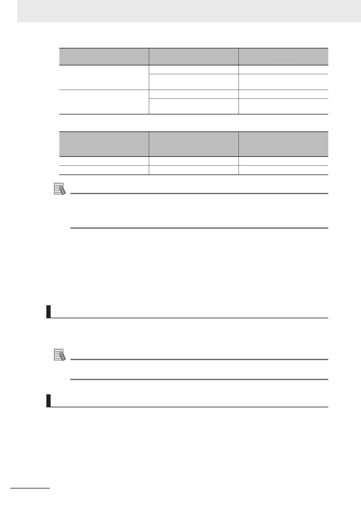
PID Control Function Selection
(J01)
Input signal IVS Operation
1: Process normal operation
4: Process normal operation, op-
posite operation available
OFF Normal operation
ON Reverse operation
2: Process inverse operation
5: Process inverse operation, op-
posite operation available
OFF Reverse operation
ON Normal operation
When PID control is disabled: Normal/reverse operation of manual frequency setting
Input Terminal [AI1, AI2] Normal/
Inverse Operation for 1st Fre-
quency Command (C53)
Input signal IVS Operation
0: Normal - Normal operation
1: Inverse - Reverse operation
Additional Information
When process control is performed by the PID control function built into the inverter, the Nor-
mal/Inverse switching “IVS” signal is used for switching normal/reverse operation of the output
(frequency setting) of the PID controller, and is not used for normal/reverse operation switching
in the manual frequency setting.
• PID differential/integral reset “PID-RST”
When “PID-RST” is turned ON, the derivative terms and integration terms of the PID controller are
reset.
• Hold PID integral component “PID-HLD”
When “PID-HLD” is turned ON, the integration terms of the PID controller are held.
Terminal Output Function
• Under PID control “PID-CTL”
When PID control is enabled and the RUN command is ON, the ON signal is output.
Additional Information
During PID control, although control is in progress, the inverter may stop as a result of the sleep
function. Even in such a case, the "PID-CTL" signal remains ON.
PID Feedback Disconnection Detection
If “0: Analog input terminals (AI1, AI2 (AII function), AI2 (AIV function))” is selected for PID Control
Feedback Selection (E119), and “5: PID feedback value” is selected for Input Terminal [AI2] Function
Selection (AII) (E62), disconnection is detected and processed as an alarm (cof alarm). At Current In-
put Wire Break Detection (H91), set whether disconnection detection is enabled or disabled, and also
set the time for judging a disconnection (a disconnection is judged when the current input of terminal
[AI2] is below 2 mA).
7 Other Functions
7-140
M1 Series Standard Type User's Manual (I669)

 Loading...


