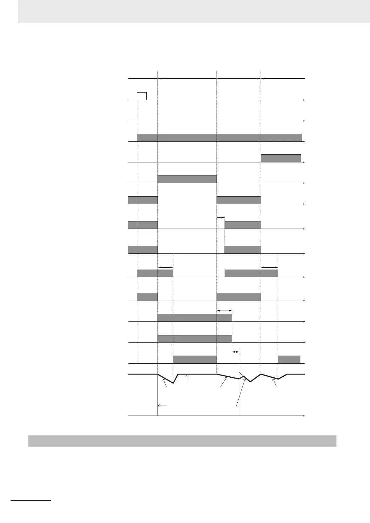
Timing diagram for commercial switching
ON
ON
ON
ON
ON
ON
ON
ON
ON
ON
ON
ON
ON
ON
ON
Commercial power supply
ON
ON
Inverter
operation Inverter operation
When switching to commercial
power supply due to occurrence of
an alarm during inverter operation
Commercial power
supply operation
↓ Alarm occurrence
Inverter
Inverter
t
t
t
t
t
t
t
t
t
t
t
t
t
t
T3
T2
H13
T1 T1
Motor free-run Motor free-runMotor free-run
Pull-in
Motor rotation
Inverter output
free-run
N
ormal
acceler
a
t
ion
RUN command
OPX
Alarm
30
Commercial power supply selection
43
Inverter primary side
MC1
Operation SW
3S
Stop SW
5S
Inverter secondary side
delay timer
T3 (ON delay)
Inverter secondary side
MC2
Commercial power supply switch
delay timer
T1 (OFF delay)
Forward command
FD
Commercial power supply switch
T2 (OFF delay)
Commercial power supply selection
CS
Commercial power supply circuit
MC3
Inverter output
and motor rotation
7-9-16
Output current fluctuation damping
When the motor is driven, the output current of the inverter may fluctuate (current fluctuation) due to
the motor characteristics or the backlash at the load machine side. This parameter increases the 1st
Output Current Fluctuation Damping Gain (H80) and 2nd Output Current Fluctuation Damping Gain
(A41) when the control function for suppressing such current fluctuation is to be adjusted.
7 Other Functions
7-144
M1 Series Standard Type User's Manual (I669)

 Loading...


