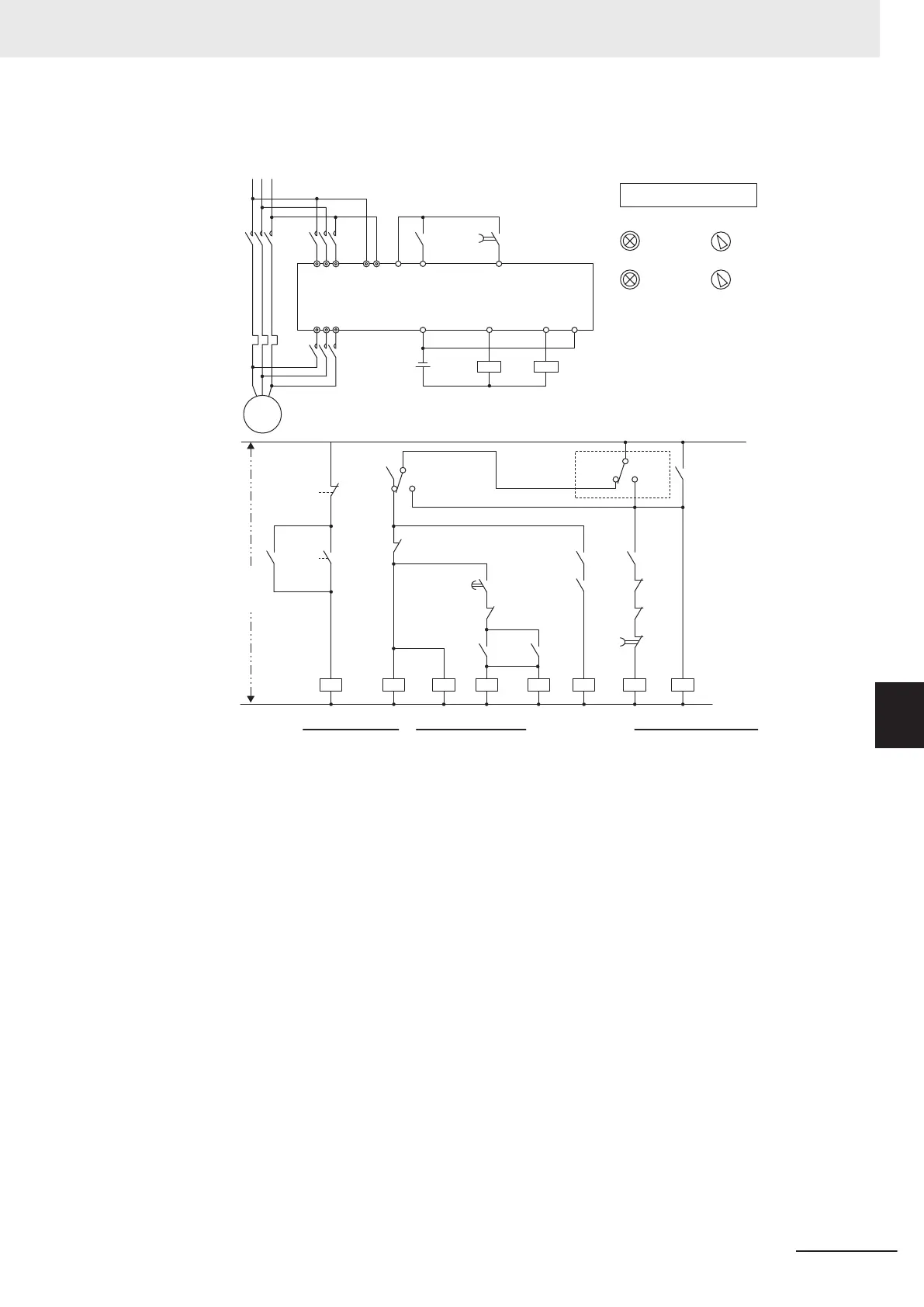
Connection example for commercial power supply operation
MC2
DC
24V
R S T RO TO CM FW DI
(CS)
ROACM
RUN
U V W ROC
(ALM)(RUN)
DO
3S
5S
43
44
INV
T2
MC3
FDT1
MC2
T3
MC1
OPX
OPX
INV
4
3
44
30
OPX
OPX
OPX
T3
E
MC3
RUN
THR
MC2
MC2
T1
E
Main power supply
Operation switch
Run
Stop
Commercial
Emergency
Control
power
supply
Inverter
Alarm
30
Forward
command
FW
Commercial
T2
Commercial
Note 1 Note 2
Emer-
gency
Alarm
30
Commercial operation
RUN command Inverter operation
MC3
THR
MC1
IM
3S
(Run)
5S
(Stop)
Normal
Emergency
switching
Normal
Note 1. Emergency switching
Manual switching performed when the sequence for switching to commercial power supply is not per-
formed normally due to a major breakdown of the inverter.
Note 2. When an alarm is issued in the inverter, switching to commercial power supply occurs automatically
.
7 Other Functions
7-143
M1 Series Standard Type User's Manual (I669)
7-9 Other Operation Functions
7
7-9-15 Commercial Switching (CS)

 Loading...


