Parameter No. Function name Data
Default da-
ta
Unit
Related function
Frequency Calculation Operation Target 1 (E131)
Frequency Calculation Operation Target 2 (E132)
Frequency Addition Sign Selection (E135)
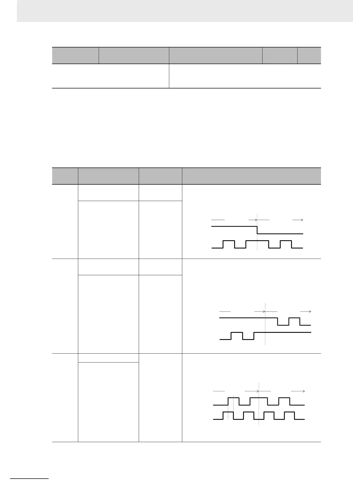
• Pulse train input method (d14)
By entering a pulse train in the input terminals [PIA] and [PIB] of the inverter control circuit, it is pos-
sible to make a frequency setting proportional to the frequency of the pulse. The pulse train input
method is specified by the Input Terminal [PIA][PIB] Pulse Input Format Selection (d14). Input can
be made in four types, namely the Pulse train signing/pulse train input, Forward and reverse pulse,
and Quadrature A/B signal (A phase lead, B phase lead).
d14 da-
ta
Target terminal
Pulse input
method
Remarks
0
Input Terminal [PIA]
Pulse train sign-
ing
A speed command corresponding to the frequency of
pulse train input is applied. Moreover, the polarity of the
speed command can be set by the pulse train signing.
Forward
Reverse
Pulse train
signing
Pulse train
input
OFF ON
Input Terminal [PIB] Pulse train input
1
Input Terminal [PIA]
Forward rota-
tion pulse
A speed command corresponding to the frequency of
pulse train input is applied. If the input pulse is a forward
rotation pulse, it results in straight polarity
, and if the in-
put pulse is a reverse rotation pulse, it results in reverse
polarity.
Forward Reverse
Reverse
rotation pulse
Forward
rotation pulse
Input Terminal [PIB]
Reverse rota-
tion pulse
2
Input Terminal [PIA]
Quadrature A/B
signal (B phase
lead)
A speed command with polarity is applied based on the
phase dif
ference and frequency, by two types of pulse
signals having a 90° phase dif
ference (B phase lead).
Forward Reverse
Phase A input
Phase B input
Phase B lead Phase B delay
90°
Input Terminal [PIB]
7 Other Functions
7-146
M1 Series Standard Type User's Manual (I669)

 Loading...


