d14 da-
ta
Target terminal
Pulse input
method
Remarks
3
Input Terminal [PIA]
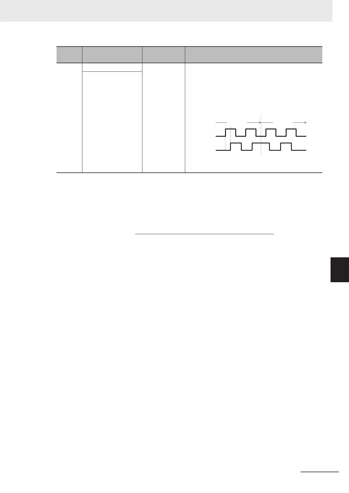
Quadrature A/B
signal (A phase
lead)
The polarity is reversed (A phase lead becomes forward
rotation) when Input Terminal [PIA][PIB] Pulse Input For-
mat Selection (d14) = 2. If the A phase and B phase are
wired in the reverse order, the polarity can be corrected
by setting Input T
erminal [PIA][PIB] Pulse Input Format
Selection (d14) = 3.
Forward Reverse
Phase A input
Phase B input
A phase lead Phase A delay
90°
Input Terminal [PIB]
• Input Terminal [PIA][PIB] Encoder Pulse Resolution (d15)
Set the number of encoder pulses of pulse train input.
• Pulse scaling factor 1 (d16), Pulse scaling factor 2 (d17)
(When Modbus coil spec. No. 001C hex RL (communication is enabled) is 1))
f* [Hz] = Np [kp/S] ×
Input Terminal [PIA][PIB] Pulse Scaling Factor Numerator (d17)
Input Terminal [PIA][PIB] Pulse Scaling Factor Denominator (d16)
f* [Hz]: Frequency set value
Np [kp/s]: Entered input pulse frequency
• Filter time constant (d18)
Set the filter time constant with respect to the pulse train input.
• PID feedback based on pulse train input (E119 = 3)
Perform the same processing as the frequency setting process for the pulse train, and convert to the
feedback value with the maximum frequency with respect to the frequency reference value of the
result as 100%. When one of the following conditions is satisfied at the same time, pulse train input
is used for both the set frequency and PID feedback.
•
Set “12: Pulse train input” to 1st Frequency Reference Selection (F01)/2nd Frequency Reference
Selection (C30).
• Set “13: Calculation result” to 1st Frequency Reference Selection (F01)/2nd Frequency Reference
Selection (C30), and set “7: Pulse train frequency” to Frequency Calculation Operation Target 1
(E131)/Frequency Calculation Operation Target 2 (E132).
• Operation frequency input setting based on pulse train input (E131/E132 = 5)
Perform the same processing as the frequency setting process for the pulse train, and set the fre-
quency reference value of the result as the selection value of the operation frequency.
7 Other Functions
7-147
M1 Series Standard Type User's Manual (I669)
7-9 Other Operation Functions
7
7-9-17 Pulse Train Frequency Input

 Loading...