8-4
Modbus Communication Protocol
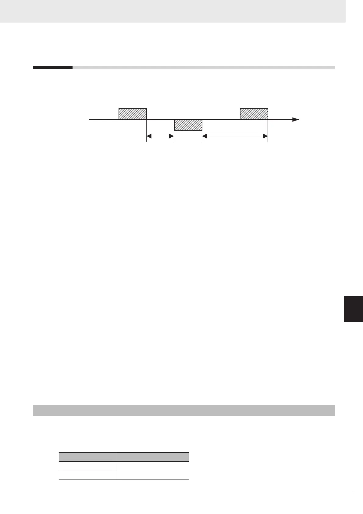
The inverter communicates with external controllers as follows.
External controller
Inverter
Time
(1) Query (1) Query
(3) Response
(2) Wait time
(Silent Interval + {y19})
(4) RS-485 Communication
(Communication time-out
detection timer) ({y18})
1. Frame (Query) that is sent from the external control device to the inverter
2. After receiving a query frame, the inverter waits the total time of the silent Interval and the RS-485
Communication Response Interval Time (y19), before returning a response.
Silent interval
The wait time that is specified on Modbus communication. Its data length is 3.5 characters (3.5
bytes).
It depends on the Modbus communication speed setting.
(Ex
am
ple
)
For 9,600 bps communications
One character: 10 bits (1 start bit + 8 data bits + 1 stop bit)
T
ime required per character: 1/9,600 (bps) × 10 (bit length) × 1,000 = 1.04 ms
Time required for 3.5 characters: 1.04 ms × 3.5 = 3.64 ms
However
, according to the Modbus specifications, this time is fixed to 1.75 ms for communications
speeds exceeding 19.2 kbps.
3. Frame (Response) that is sent from the inverter back to the external controller.
4. After sending a response, the inverter monitors the time until it completes receiving the query
frame from the external control device. The inverter judges it as a communications error if it re-
ceives no response within the RS-485 Communication Timeout Time (y18).
Then, the inverter operates according to the Operation Selection on Communication Error (y12),
while waiting for the reception of the first data again.
The monitoring of the Communication Error T
imeout Time starts from the first sending/receiving
operation is established after the power supply is cycled or after the inverter is reset.
The inverter does not recognize as a communications error timeout if the sending/receiving opera-
tion is not established at all.
8-4-1
Message Configuration
The command message sent from the master to a slave (or slaves) is called a “query” and the re-
sponse message returned from the slave(s) is called a “response.” The transmission format of a query/
response is as follows.
Query Response
Slave address Confirmation slave address
Function code Confirmation function code
8 Communications Functions
8-7
M1 Series Standard Type User's Manual (I669)
8-4 Modbus Communication Protocol
8
8-4-1 Message Configuration

 Loading...


