*3. After receiving data from the master inverter, the management inverter sends the next master switching com-
mand with a wait time of “silent interval + Communication Wait Time (y19).” If the management inverter cannot
receive the data sent from the master inverter within the Communication Error Timeout T
ime (y18), a commu-
nication timeout occurs and the management inverter follows the operation set in the Operation Selection on
Communication Error (y12).
*4. Be sure to enable the Communication Error Timeout Time setting (y18 = 0.01 to 99.99) on the management
inverter. When this setting is disabled (y18 = 0), the co-inverter communication will stop if the management
inverter cannot receive data from the master inverter. In this case, cycle the power supply for the manage-
ment inverter, or reset the management inverter (by turning ON/OFF the terminal RS).
8-8-1
Co-inverter Communication Parameters
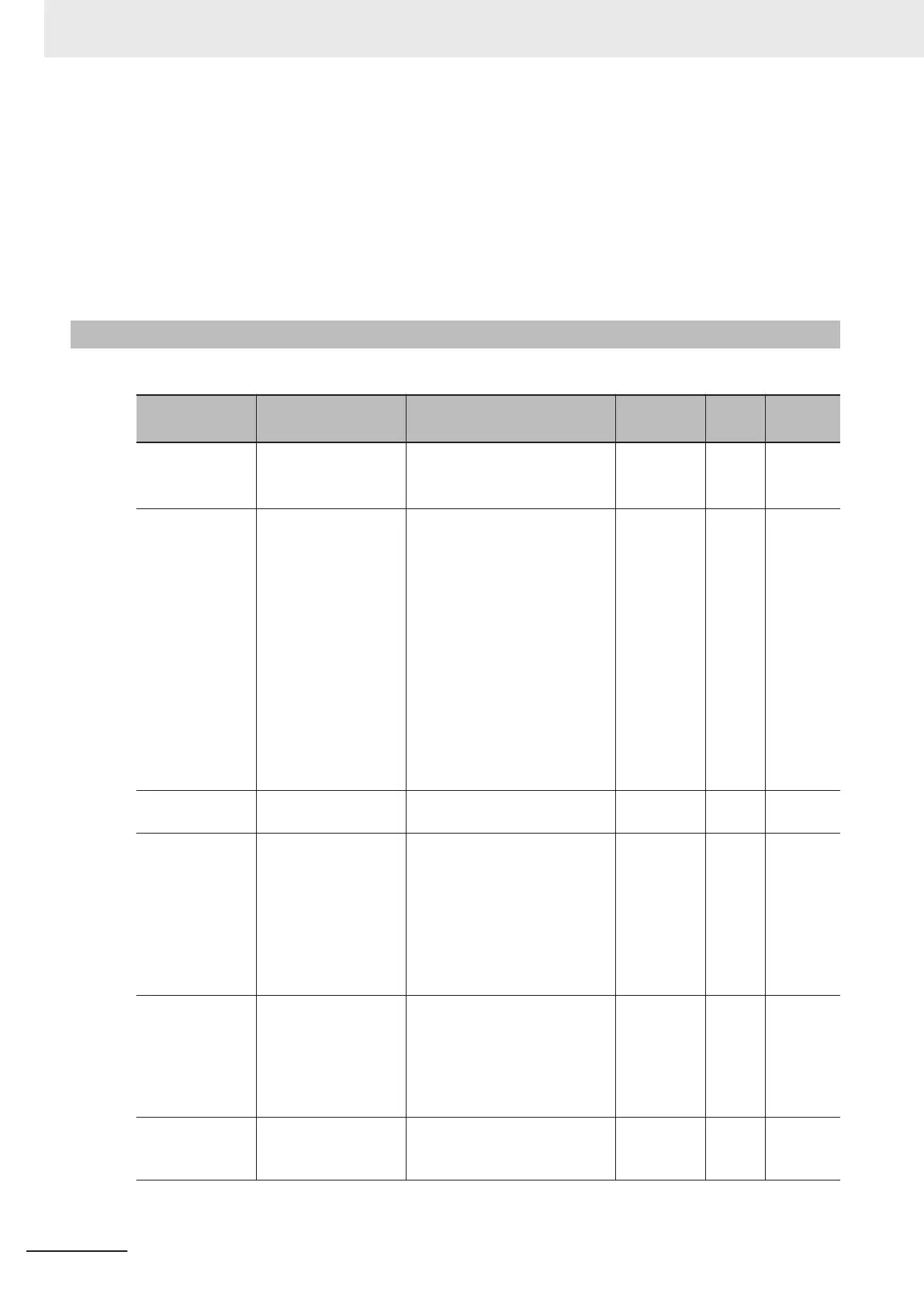
The parameters required to establish co-inverter communication are shown in the table below.
Parameter No. Function name Data
Default da-
ta
Unit
Setting
target
*1
y11
*2
RS-485 Communica-
tion Station No. Se-
lection
1 to 255
*3
(250 to 255: Simultaneous
broadcasting by group)
1 -
ALL
*4
y12
*5
Operation Selection
on Communication
Error
0: Immediately trip with alarm
ErP
1: T
rip with alarm ErP after run-
ning for the period specified by
timer y003
2: Retry during the period
specified by timer y003. If the
retry fails trip with alarm ErP. If
it succeeds continue to run.
3: Continue to run
1
1: Trip with alarm ErP after de-
celeration stop
13: Free run stop
14: Deceleration stop
0 - ALL
y13
RS-485 Error Detec-
tion Timer
0.0 to 60.0 s 2.0 s
ALL
y14
RS-485 Communica-
tion Baud Rate
0: 2400 bps
1: 4800 bps
2: 9600 bps
3: 19200 bps
4: 38400 bps
5: 57600 bps
6: 76800 bps
7: 115200 bps
2 -
ALL
y16
RS-485 Communica-
tion Parity Bit Selec-
tion
0: None (Stop bit: 2 bits)
1: Even number parity (Stop bit:
1 bits)
2: Odd number parity (Stop bit:
1 bits)
3: None (Stop bit: 1 bits)
3 - ALL
y18
RS-485 Communica-
tion Timeout Time
0: Not check of the time-out
(OFF)
1 to 60 s
0.0
s ALL
8 Communications Functions
8-28
M1 Series Standard Type User's Manual (I669)

 Loading...


