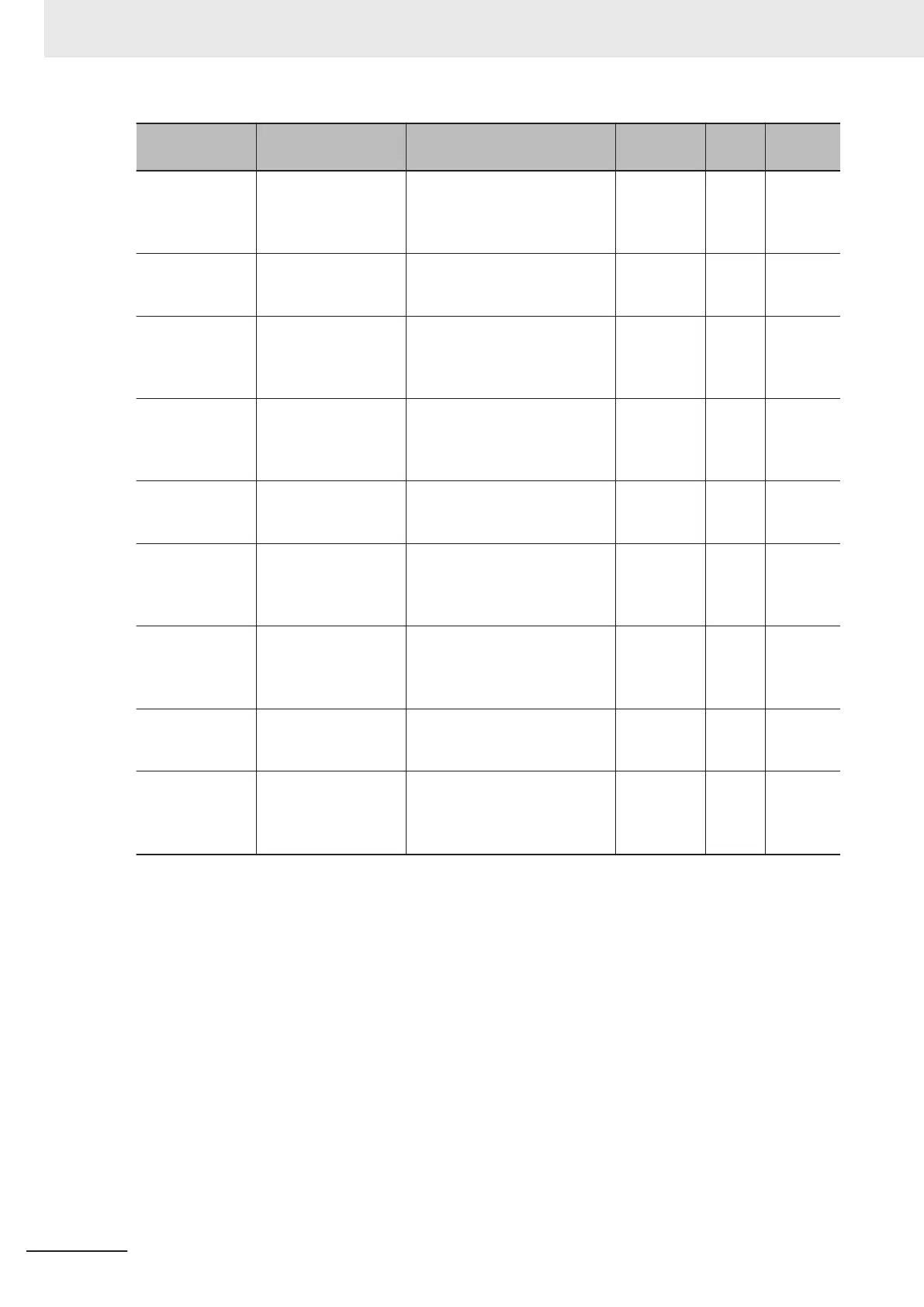
Parameter No. Function name Data
Default da-
ta
Unit
Setting
target
*1
H347
Recipient Register of
All Stations in Co-in-
verter Communica-
tion 3
0000 to FFFF Hex 0000 - M
H348
Sender Register of All
Stations in Co-inver-
ter Communication 3
0000 to FFFF Hex 0000 - M
H349
Recipient Station
Number of All Sta-
tions in Co-inverter
Communication 4
1 to 247
*10
4 - M
H350
Recipient Register of
All Stations in Co-in-
verter Communica-
tion 4
0000 to FFFF Hex 0000 - M
H351
Sender Register of All
Stations in Co-inver-
ter Communication 4
0000 to FFFF Hex 0000 - M
H352
Recipient Station
Number of All Sta-
tions in Co-inverter
Communication 5
1 to 247
*10
5 - M
H353
Recipient Register of
All Stations in Co-in-
verter Communica-
tion 5
0000 to FFFF Hex 0000 - M
H354
Sender Register of All
Stations in Co-inver-
ter Communication 5
0000 to FFFF Hex 0000 - M
E01 to E05, E98,
E99
Input Terminal [DI1]
Function Selection to
Input T
erminal [DI7]
Function Selection
160: 485 (Start co-inverter
communication)
*8
- -
A
*1. Below are the details of the setting target.
ALL: Setting required for all connected inverters
A: Setting required only for management inverter (Station No. 1)
B: Setting required for inverters other than management inverter (Station No. 1)
M: Setting required only for inverters set in H304 to H305 (= Inverters assigned with master role)
*2. After changing any of the y11 and H303 to H306 data on the management inverter, be sure to cycle the
power supply to apply the changes. For inverters other than the management inverter, these changes will be
applied immediately. However
, for inverters other than the management inverter, if y11 is changed to Station
No. 1 (Management Inverter), be sure to cycle the power supply to apply the changes. (Station Nos. 2 to
247 will apply changes immediately.)
*3. To switch the master inverter among more than one inverter, be sure to set sequential station numbers. If
the set station numbers include any skipped number, communications cannot be established.
*4. For the management inverter, set the station number to 1 (y11 = 1).
*5. When the Operation Selection on Communication Error (y12) is set to other than “3: Continue to run” on the
management inverter, the co-inverter communication session will stop if a communications timeout error oc-
curs on the management inverter. In this case, cycle the power supply of the management inverter.
*6. When Co-Inverter Communication Function Selection (H303) is set to “1: Co-inverter communication” or “2:
Co-inverter communication (Management Inverter),” co-inverter communication will be possible.
*7. Set these parameters so that H304 is equal to or less than H305.
8 Communications Functions
8-30
M1 Series Standard Type User's Manual (I669)
 Loading...


