8-9
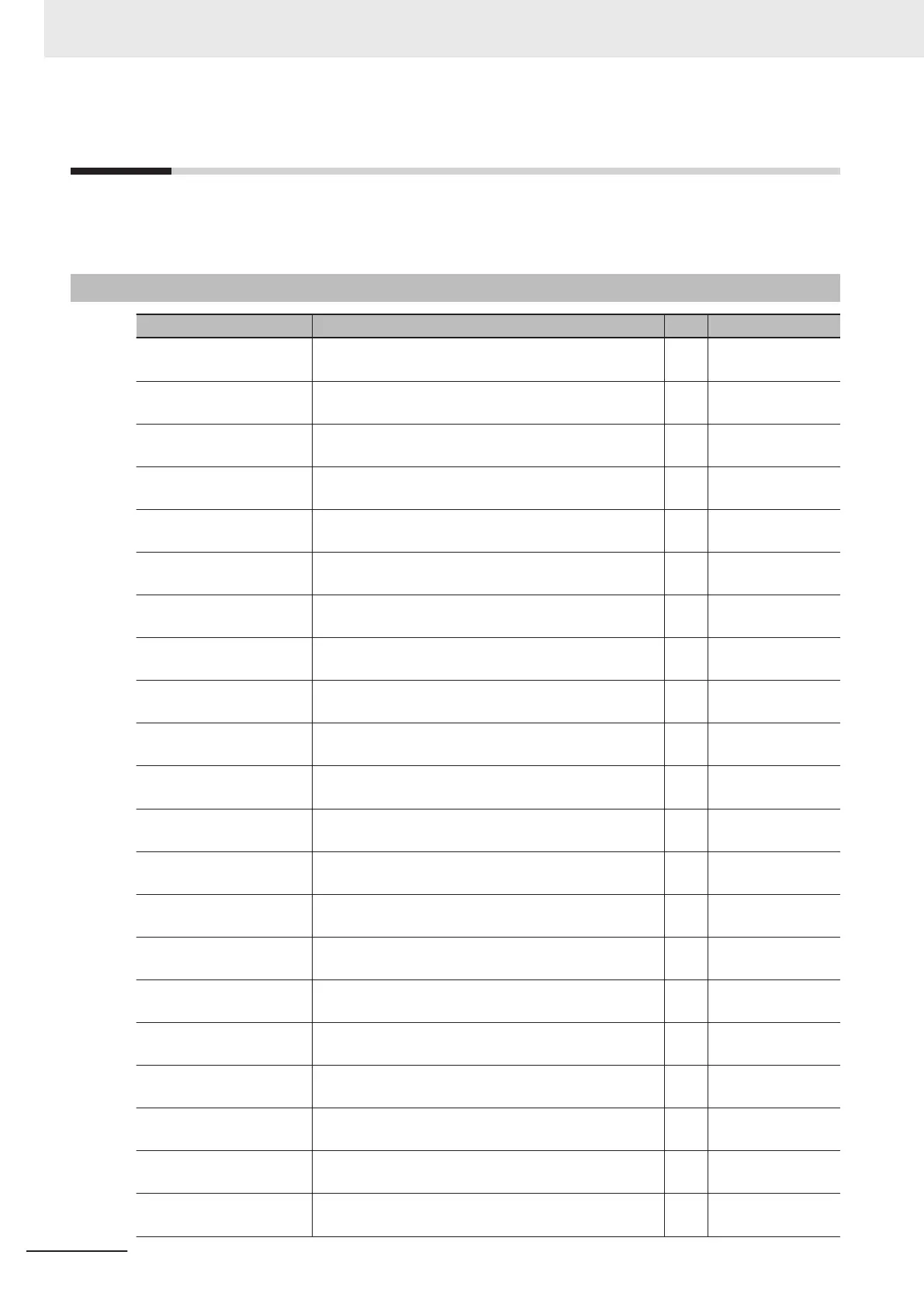
Modbus Communication Data Lists
R/W in the list shows whether data can be read from, or written to, the coil or holding register.
(R: Read only, R/W: Read and write enabled)
8-9-1
Coil Number List
Modbus coil spec. No. Item R/W Description
0000 hex FW (Forward run) R/W
1: ON
0: OFF
0001 hex RV (Reverse run) R/W
1: ON
0: OFF
0002 hex
DI1 (Multifunction input 1)
*1
R/W
1: ON
0: OFF
0003 hex
DI2 (Multifunction input 2)
*1
R/W
1: ON
0: OFF
0004 hex
DI3 (Multifunction input 3)
*1
R/W
1: ON
0: OFF
0005 hex
DI4 (Multifunction input 4)
*1
R/W
1: ON
0: OFF
0006 hex
DI5 (Multifunction input 5)
*1
R/W
1: ON
0: OFF
000D hex
DI6 (Multifunction input 6)
*1
R/W
1: ON
0: OFF
000E hex
DI7 (Multifunction input 7)
*1
R/W
1: ON
0: OFF
000F hex RS (Reset) R/W
1: ON
0: OFF
0010 hex FWR (During forward rotation) R
1: ON
0: OFF
0011 hex RVR (During reverse rotation) R
1: ON
0: OFF
0012 hex EXT (During DC braking or during pre-exciting) R
1: ON
0: OFF
0013 hex INT (Inverter shut down) R
1: ON
0: OFF
0014 hex BRK (During braking) R
1: ON
0: OFF
0015 hex NUV (DC link circuit voltage established) R
1: ON
0: OFF
0016 hex TL (Torque limiting) R
1: ON
0: OFF
0017 hex VL (During voltage limiting) R
1: ON
0: OFF
0018 hex IL (During current limiting) R
1: ON
0: OFF
0019 hex ACC (During acceleration) R
1: ON
0: OFF
001A hex DEC (During deceleration) R
1: ON
0: OFF
8 Communications Functions
8-34
M1 Series Standard Type User's Manual (I669)

 Loading...


