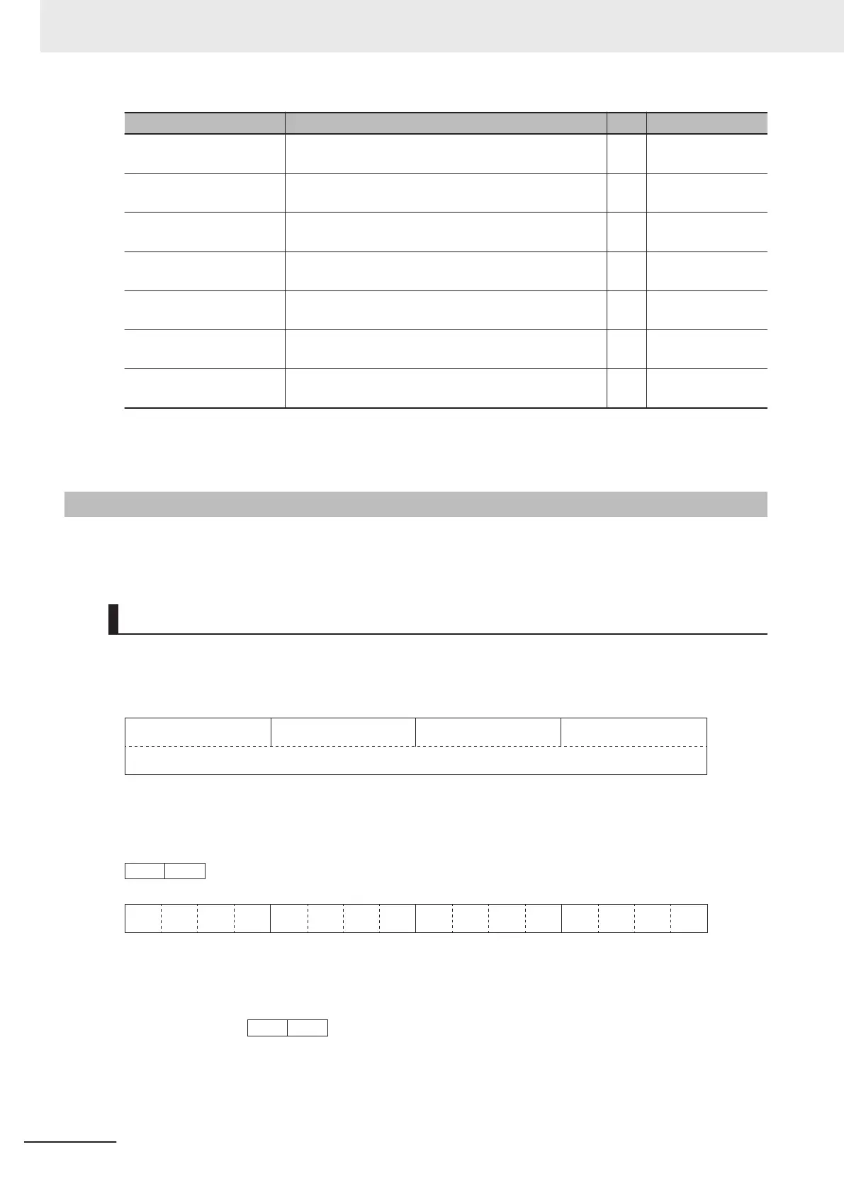
Modbus coil spec. No. Item R/W Description
003B hex EN (Safety) R
1: ON
0: OFF
003D hex DI6 (Multifunction input 6) R
1: ON
0: OFF
003E hex DI7 (Multifunction input 7) R
1: ON
0: OFF
003F hex RS (Reset) R
1: ON
0: OFF
0040 hex DO1 (Multifunction output terminal 1) R
1: ON
0: OFF
0041 hex DO2 (Multifunction output terminal 2) R
1: ON
0: OFF
0048 hex RO (Multifunction relay output) R
1: ON
0: OFF
*1. You can turn ON/OFF terminal input using Modbus communications by setting “4. RS-485 communication”
in 1st RUN Command Selection (F02)/2nd RUN Command Selection (E102). For details on the relationship
between terminal block input and ON status, refer to 7-2-1 Multifunction Input Selection on page 7-26.
8-9-2
Register List
The following describes the data format and register Nos. when parameters are accessed via Modbus
communication.
Data Format Specification
All data in the data field of a communications frame is represented as 16-bit binary data as shown be-
low.
16-bit binary data
15
14 13 12 11 10 9 8 7 6 5 4 3 2
1 0
For convenience of description, 16-bit data is divided into the upper byte (8 bits from 15 to 8) and the
lower byte (8 bits from 7 to 0) and represented in hexadecimal.
For example, the following data is 1234 hex in hexadecimal representation and is described as
.
0 0 0 1 0 0 1 0 0 0 1 1 0 1 0
0
Data Format [1]: Integer Data (Positive), Resolution 1
Example: 1st Rated Voltage at Base Frequency (F05) = 200 V
200 = 00C8 hex →
Data Format [2]: Integer Data (Positive/Negative), Resolution 1
Example: -20
8 Communications Functions
8-36
M1 Series Standard Type User's Manual (I669)

 Loading...


