-20 = FFEC hex →
Data Format [3]: Decimal Point Data (Positive), Resolution 0.1
Example: 1st Maximum Output Frequency (F03) = 70.0 Hz
70.0 × 10 = 700 = 02BC hex →
Data Format [4]: Decimal Point Data (Positive/Negative), Resolution 0.1
Example: Input Terminal [AI1] Offset (C31) = -5.0%
-5.0 × 10 = -50 = FFCE hex →
Data Format [5]: Decimal Point Data (Positive), Resolution 0.01
Example: Multi-step Frequency Reference 1 (C05) = 50.25 Hz
50.25 × 100 = 5,025 = 13A1 hex →
Data Format [6]: Decimal Point Data (Positive/Negative), Resolution 0.01
Example: Torque Value (M07) = -85.38%
-85.38 × 100 = -8,538 = DEA6 hex→
Data Format [7]: Decimal Point Data (Positive), Resolution 0.001
Example: Electronic Thermal for Braking Resistor Allowable Average Loss (F51) = 0.105 kW
0.105 × 1,000 = 105 = 0069 hex →
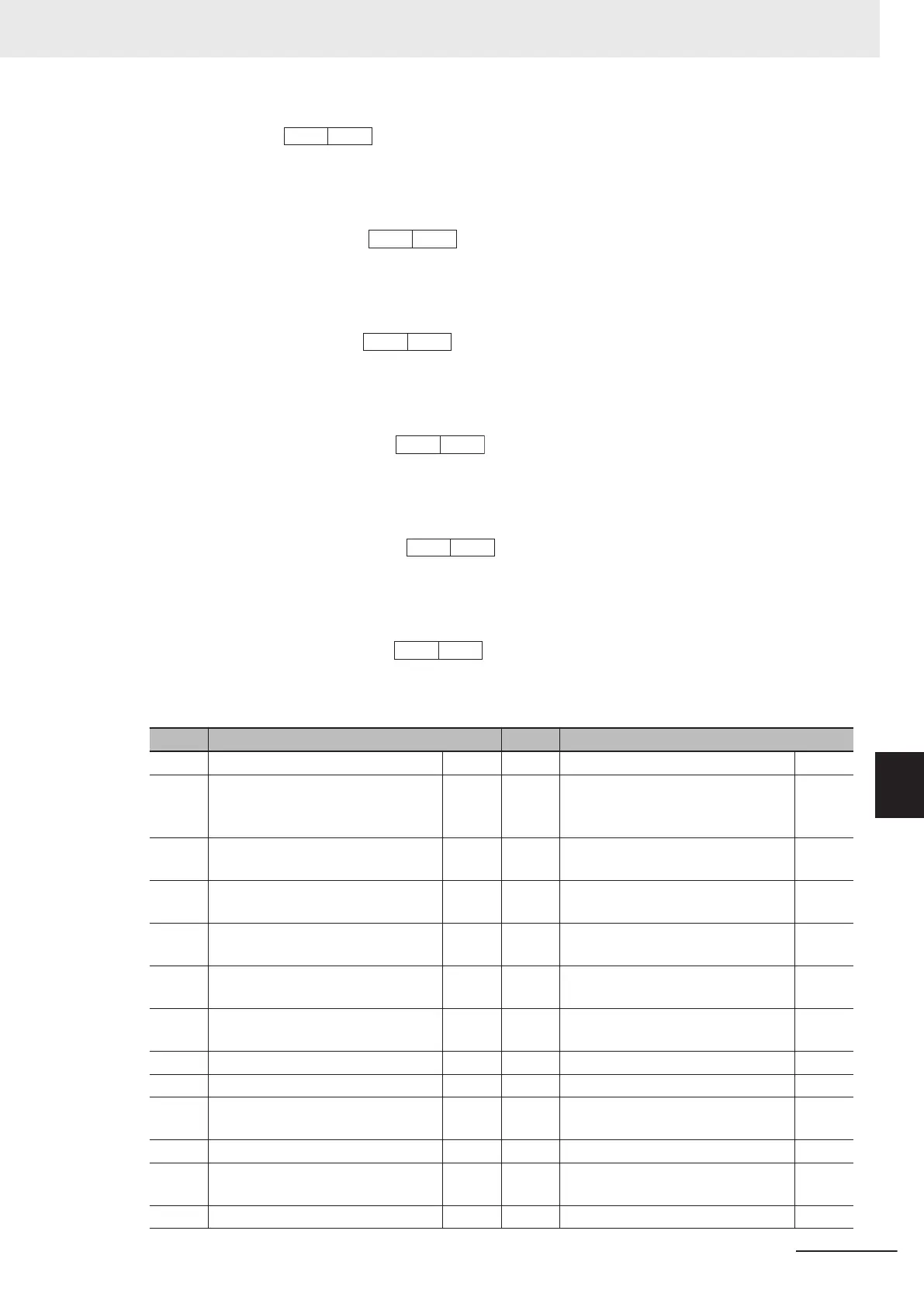
Data Format [10]: Alarm Code
Code Description Code Description
0 No alarm --- 37 Tuning Error er7
1 Overcurrent Protection (During Ac-
celeration)
0c1 42 Step-out Detection/Magnetic Pole
Position Detection Error during
Startup
erd
2 Overcurrent Protection (During De-
celeration)
0c2 46 Output Phase Loss Error 0pl
3 Overcurrent Protection (During
Constant Speed)
0c3 47 Speed Mismatch or Excessive
Speed Deviation
ere
6 Overvoltage Protection (During Ac-
celeration)
0u1 50 Magnetic Pole Position Detection
Error
erc
7 Overvoltage Protection (During De-
celeration)
0u2 51 Data Save Error during Undervolt-
age
erf
8 Overvoltage Protection (During
Constant Speed)
0u3 52 Excessive Position Deviation Error d0
10 Undervoltage lu 53 RS-485 Communication Error erp
11 Input Phase Loss Error lin 54 Hardware Error erh
16 Inrush Current Prevention Circuit
Error
pbf 56 Positioning Control Error ero
17 Cooling Fin Overheat Error 0h1 57 Enable Circuit Failure ecf
18 External Trip 0h2 58 Terminal [Ai2]AII Current Input Wire
Break Detection
cof
19 Inverter Overheat Error 0h3 59 Breaking Transistor Error dba
8 Communications Functions
8-37
M1 Series Standard Type User's Manual (I669)
8-9 Modbus Communication Data Lists
8
8-9-2 Register List
 Loading...


