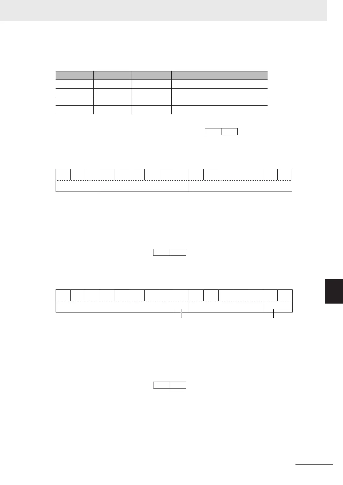
Polarity: 0 → Positive (+), 1 → Negative (-), Exponent part: 0 to 3, Mantissa part: 1 to 999
Value represented in this format = (Polarity) mantissa part × 10 to the power of (exponent part - 2)
Value Mantissa part Exponent part 10 to the power of (exponent part - 2)
0.01 to 9.99 1 to 999 0 0.01
10.0 to 99.9 100 to 999 1 0.1
100 to 999 100 to 999 2 1
1,000 to 9,990 100 to 999 3 10
Example: 1st Acceleration Time 1 (F07) = 20.0 s
20.0 = 200 × 0.1 → 0000 0100 1
100 1000
b
= 04C8 hex →
Data Format [14]: Operation Command
General-purpose
input
15 14 13 12 11 10 9 8 7 6 5 4 3 2 1 0
0 0 0
Not used General-purpose input
RST DI7 DI6 0 0 0 DI5 DI4 DI3 DI2 DI1 REV FWD
RST: Alarm reset
FWD: Forward command
REV: Reverse command
(All bits are ON with 1 regardless of the positive/negative logic setting.)
Example: Operation command
(S06) = FWD, DI1 = ON
0000 0000 0000 0101
b
= 0005 hex →
Data Format [15]: General-purpose Output Terminal
15 14 13 12 11 10 9 8 7 6 5 4 3 2 1 0
0 0
0
Not used
General-purpose output
0 0 RO
DO2 DO1
0 0 0 0 0 0 0 0
General-purpose output
Not used
RO: Relay output
FWD: Forward command
REV
: Reverse command
(All bits are ON with 1 regardless of the positive/negative logic setting.)
Example:
Output T
erminal Monitor (M15) DO1 = ON
0000 0000 0000 0001
b
= 0001 hex →
Data Format [16]: Operation Status
8 Communications Functions
8-39
M1 Series Standard Type User's Manual (I669)
8-9 Modbus Communication Data Lists
8
8-9-2 Register List
 Loading...


