Operation status
1
5
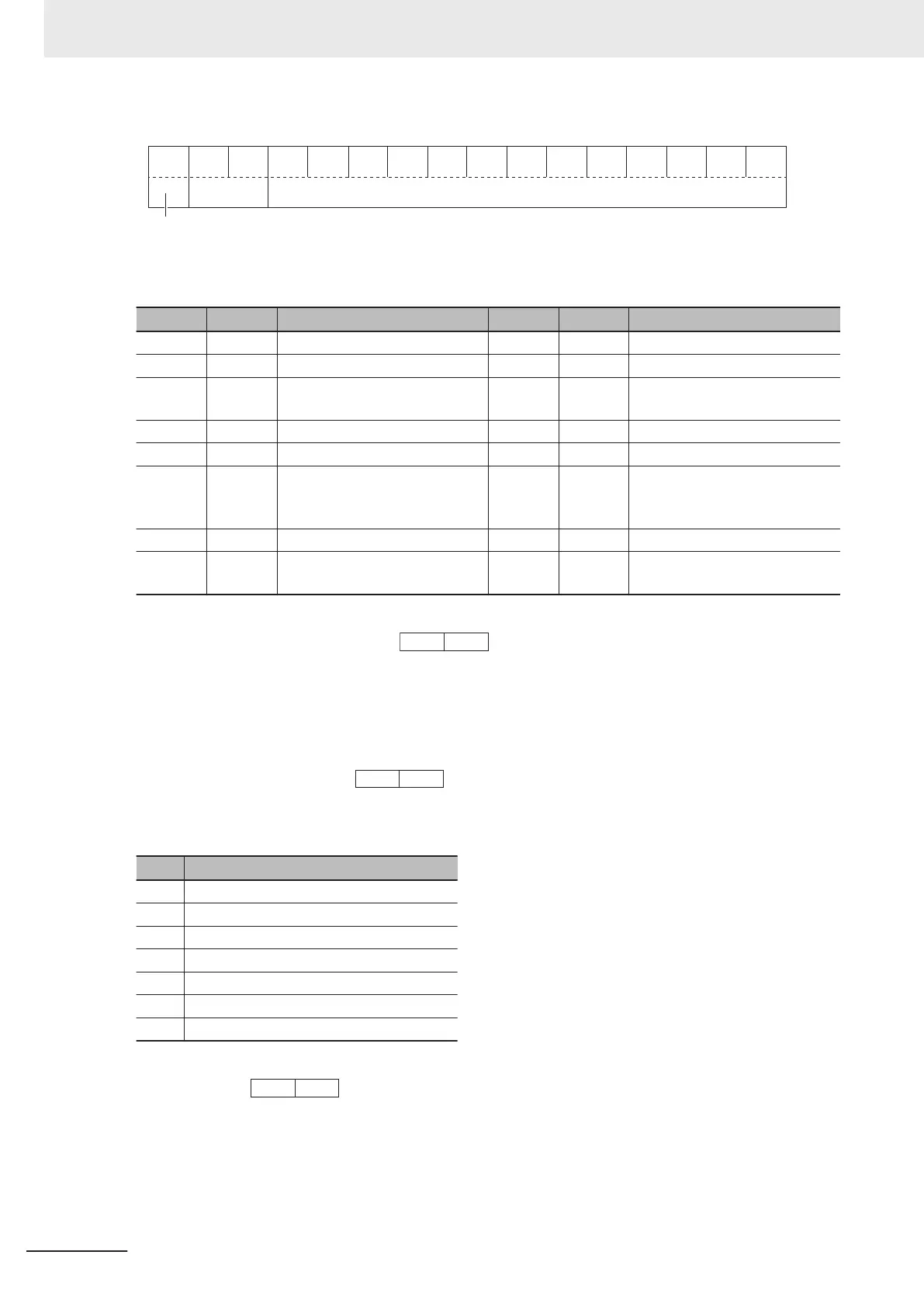
14 13 12 11 10 9 8 7 6 5 4 3 2 1 0
00
Not used Operation status
BUSY
ALMRL TL NUV BRK INT EXT REV FWDDEC
ACC
IL VL
(All bits are ON or active with 1.)
Bit Symbol Description Bit Symbol Description
0 FWD During forward operation 8 IL During current limiting
1 REV During reverse operation 9 ACC During acceleration
2 EXT Direct DC braking
(or during pre-exciting)
10 DEC During deceleration
3 INT Inverter shut down 11 ALM Alarm relay
4 BRK During braking 12 RL Communications effective
5 NUV Main circuit DC voltage estab-
lished
(Undervoltage with 0)
13 0 ---
6 TL Torque limiting 14 0 ---
7 VL During voltage limiting 15 BUSY During parameter code data
writing
Example: Operation Status 1 Monitor (M14) = During forward operation and during acceleration
0000 0010 0000 0001
b
= 0401 hex →
Data Format [19]: Current Value
A current value is decimal point data (positive), resolution 0.01.
Example: 1st Motor Electronic Thermal Level (F11) = 3.60 A
3.60 ×100 = 360 = 0168 hex →
Data Format [20]: Communications Error Code
Code Description
1 Non-existent parameter No. specified
2 Non-existent parameter No. specified
3 Improper data (Range error)
7 NAK (Link priority, no right, write disabled)
71 Checksum error, CRC error
72 Parity error
73 Framing error, overrun error, buffer full
Example: Improper address
2 = 0002 hex →
Data Format [21]: Auto Tuning
8 Communications Functions
8-40
M1 Series Standard Type User's Manual (I669)
 Loading...


