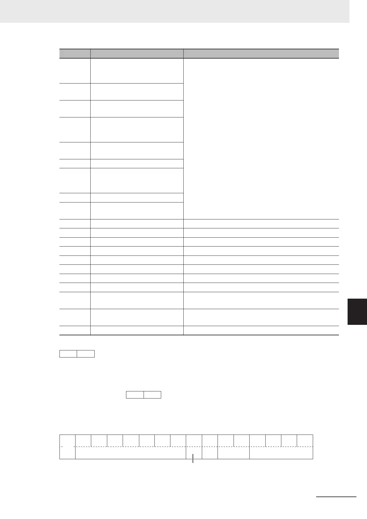
Code Description Remarks
0 Digital Operator (Increment/Decre-
ment key) (No output frequency
takeover)
Same as the selection for Frequency Reference Selection
(F01/C30)
1 Analog voltage input (terminal
[AI1])
2 Analog current input (terminal [AI2]
(AII))
3 Analog voltage input (terminal
[AI1]) + analog current input (termi-
nal [AI2] (AII))
5 Analog voltage input (terminal AI2
(AIV))
7 UP/DOWN control
8 Digital Operator (Increment/Decre-
ment key) (Output frequency take-
over)
10 Pattern operation
13 Pulse train input or Frequency cal-
culation
21 RS-485 communications
22 Fieldbus (Reserved)
23 Support Tool
24 Multi-step Frequency
25 Jogging Frequency
30 PID Control Operator Process
31 PID Control Analog Process
33 PID Control UP/DOWN control
34 PID Control Communication Proc-
ess
36 PID Control Multi-Step Terminal
Process
255 Not Selected
Example: Frequency and PID Command Source Monitor (W29) = 000A hex
→ 10 = Pattern operation
Data Format [74]: Integer Data (Positive), in 10 Hours
Example: 1st Remaining Time before the Next Motor Maintenance (M81) = 12,340 h
12340 ÷ 10 = 04D2
h
→
Data Format [76]: Operation Status 2
15 14 13 12 11 10 9 8 7 6 5 4 3 2 1 0
Not
used
During speed control
Not used
Selected
motor
Control method
Drive
motor
type
8 Communications Functions
8-45
M1 Series Standard Type User's Manual (I669)
8-9 Modbus Communication Data Lists
8
8-9-2 Register List
 Loading...


