Signal name Description
Control method Indicates the final control method including set value, terminal status, etc.
0: IM V/f control
1: IM Dynamic torque vector control without speed sensor
3: IM V/f control with speed sensor
4: IM Dynamic torque vector control with speed sensor
5: IM Vector control without speed sensor
6: IM Vector control with speed sensor
15: PM V
ector control without speed and pole position sensor
16: PM Vector control with speed and pole position sensor
Others: Reserved
Selected motor Indicates the selected motor number.
00
b
: 1st motor
01
b
: 2nd motor
During speed control 1 during control
Drive motor type 0: Induction motor
1: Synchronous motor
Example: Running Status 2 Monitor (M74) = 0003 hex
→ 0000 0000 0000 0011
b
= IM V/f control with speed sensor, 1st motor, indication motor
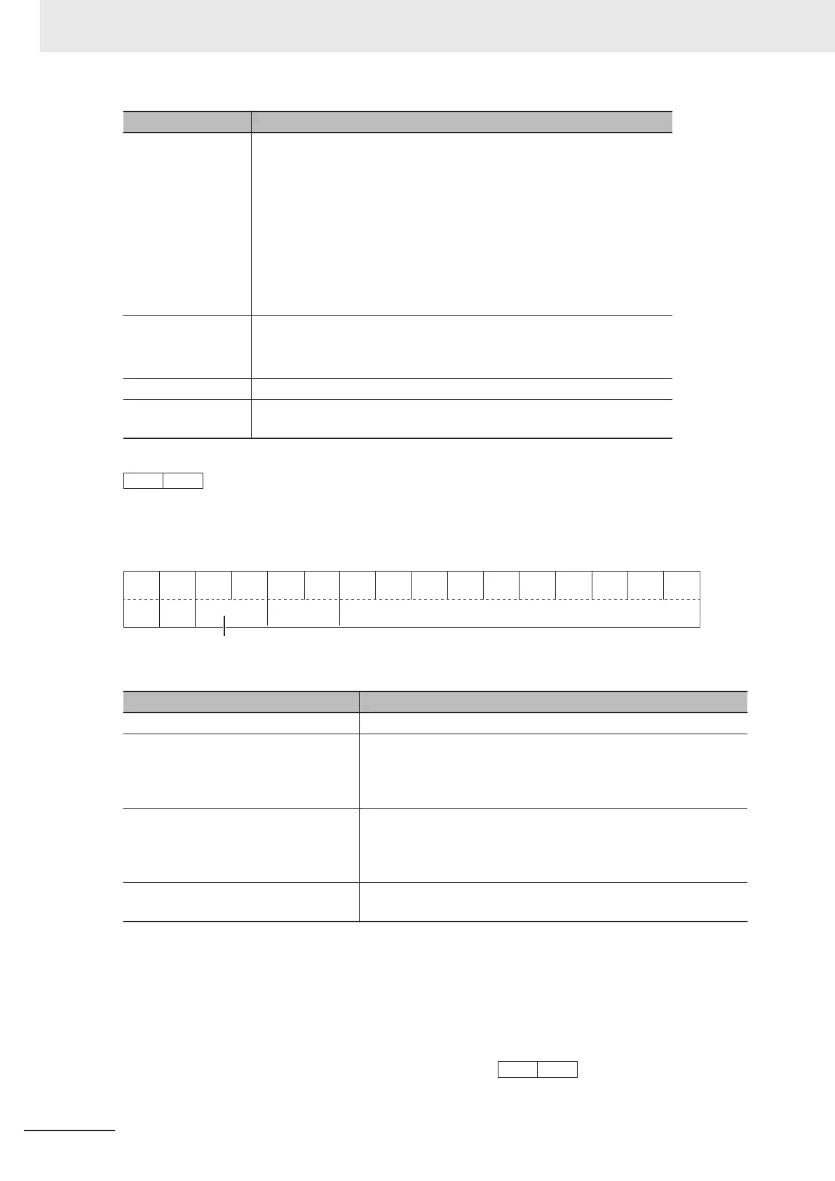
Data Format [84]: Pattern Operation
15 14 13 12 11 10 9 8 7 6 5 4 3 2
1 0
Not
used
Acceleration/Deceleration time selection
Rotation
direction
Minimum unit of
operation time
Data part of operation time
Item Description
Rotation direction 0: Forward, 1: Reverse
Acceleration/Deceleration time selection 0: 1st Acceleration T
ime 1 (F07)/
1st Deceleration Time 1 (F08)
1: 2nd Acceleration Time 1 (E10)/2nd Deceleration Time 1 (E11)
2: 1st Acceleration Time 2 (E12)/1st Deceleration Time 2 (E13)
3: 2nd Acceleration Time 2 (E14)/2nd Deceleration Time 2 (E15)
Minimum unit of operation time 0: 0.01
1: 0.1
2: 1
3: 10
Data part of operation time Exponent part 0: 000 to 999
Exponent part not 0: 100 to 999
Example: Pattern Operation Stage 1 Operation Setting (C22) = Reverse, 2nd Acceleration/Deceler-
ation Time, and 10.0 s
Rotation direction: Reverse (8000 hex)
Acceleration/Deceleration time: 2nd Acceleration/Deceleration Time (1000 hex)
Operation time: 10.0 s = 0.1 × 100 (0400 hex + 0064 hex)
Therefore, the set value is
8000 hex + 1000 hex + 0400 hex + 0064 hex = 9464 hex →
8 Communications Functions
8-46
M1 Series Standard Type User's Manual (I669)
 Loading...


