Alarm
code
Alarm
sub-
code
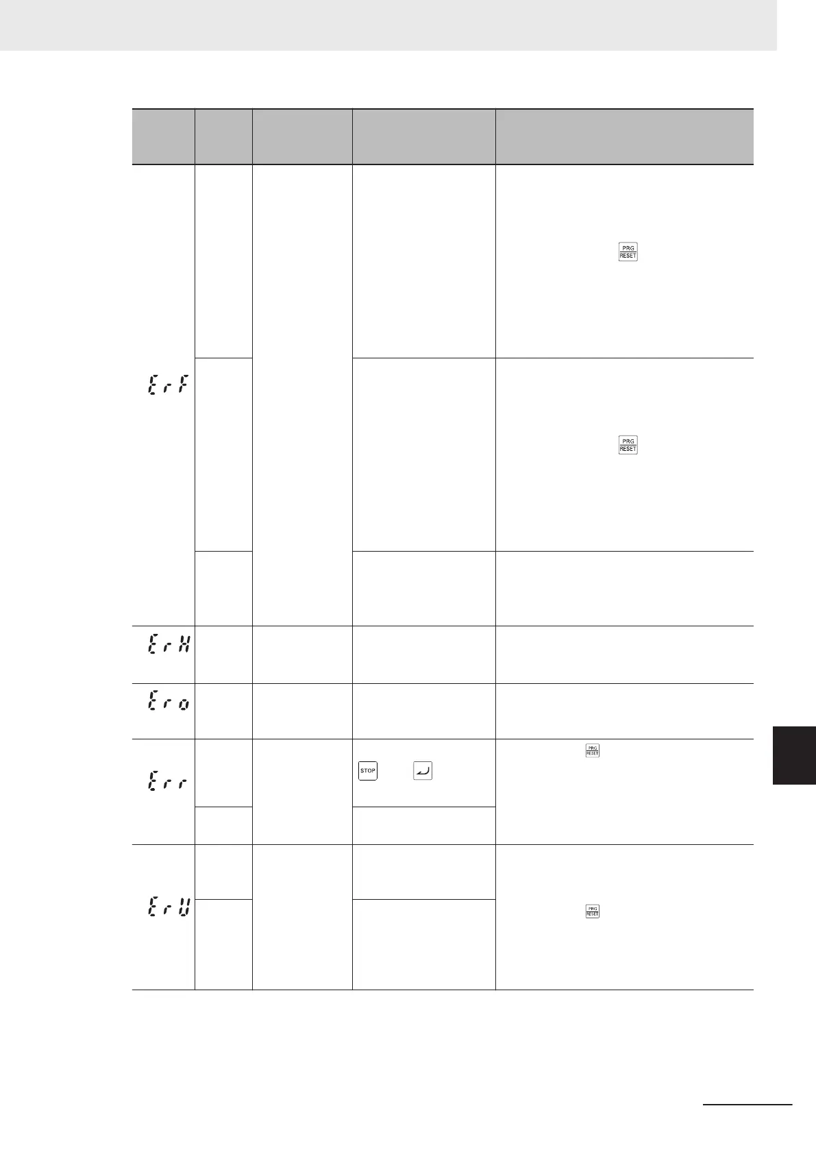
Name Description Check point and remedy reference
(ErF)
Data save error
in case of un-
dervoltage
(1) During data save at
power interruptions, the
control power supply
dropped suddenly as a
result of rapid dis-
charge of the Main Cir-
cuit DC V
oltage, etc.
Check the power drop time at Main Circuit
DC Voltage at power interruption.
→ Eliminate the cause of rapid discharge
of the Main Circuit DC Voltage, etc. Af-
ter pressing the
key to cancel the
alarm, return the commands for fre-
quency reference, PID command, and
UP/DOWN signals set from the Digital
Operator to their original settings, and
restart operation.
(2) Strong noise re-
ceived from surrounds
during data saving at
power interruption.
Check methods for measures against noise
(grounding conditions, control/main circuit
wiring and installation).
→ Implement measures against noise. Af-
ter pressing the key to cancel the
alarm, return the commands for fre-
quency reference, PID command, and
UP/DOWN signals set on the Digital
Operator to their original settings, and
restart operation.
(3) Error occurred in
control circuit
Check that erf occurs every time at power
on.
→ Board (including CPU) error, so contact
OMRON.
(ErH)
Hardware error
(1) Error in combination
of control PCB and
power PCB
Replacement of control PCB or power PCB
is necessary.
→ Please contact OMRON.
(Ero)
Position control
error
(1) Position control sys-
tem insuf
ficient gain
(servo lock)
Readjust Servo Lock Gain (J97) and Speed
Control 1 P Proportional Gain (d03).
(Err)
Mock alarm
(1) Press and hold the
key + key for
five seconds or longer.
→
Press the
key to reset.
(2) Parameter H45
(Mock Alarm) set to 1.
(ErU)
Tool communi-
cation discon-
nection
(1) A disconnection oc-
curred on the tool dur-
ing a test run.
Check if the USB cable or a connector is dis-
connected.
(2) A disconnection oc-
curred on the tool dur-
ing forced status
changing of multifunc-
tion output.
→
Press the
key to reset.
9 Troubleshooting
9-13
M1 Series Standard Type User's Manual (I669)
9-1 Alarm Display and Remedies
9
9-1-2 Alarm Code List
 Loading...


