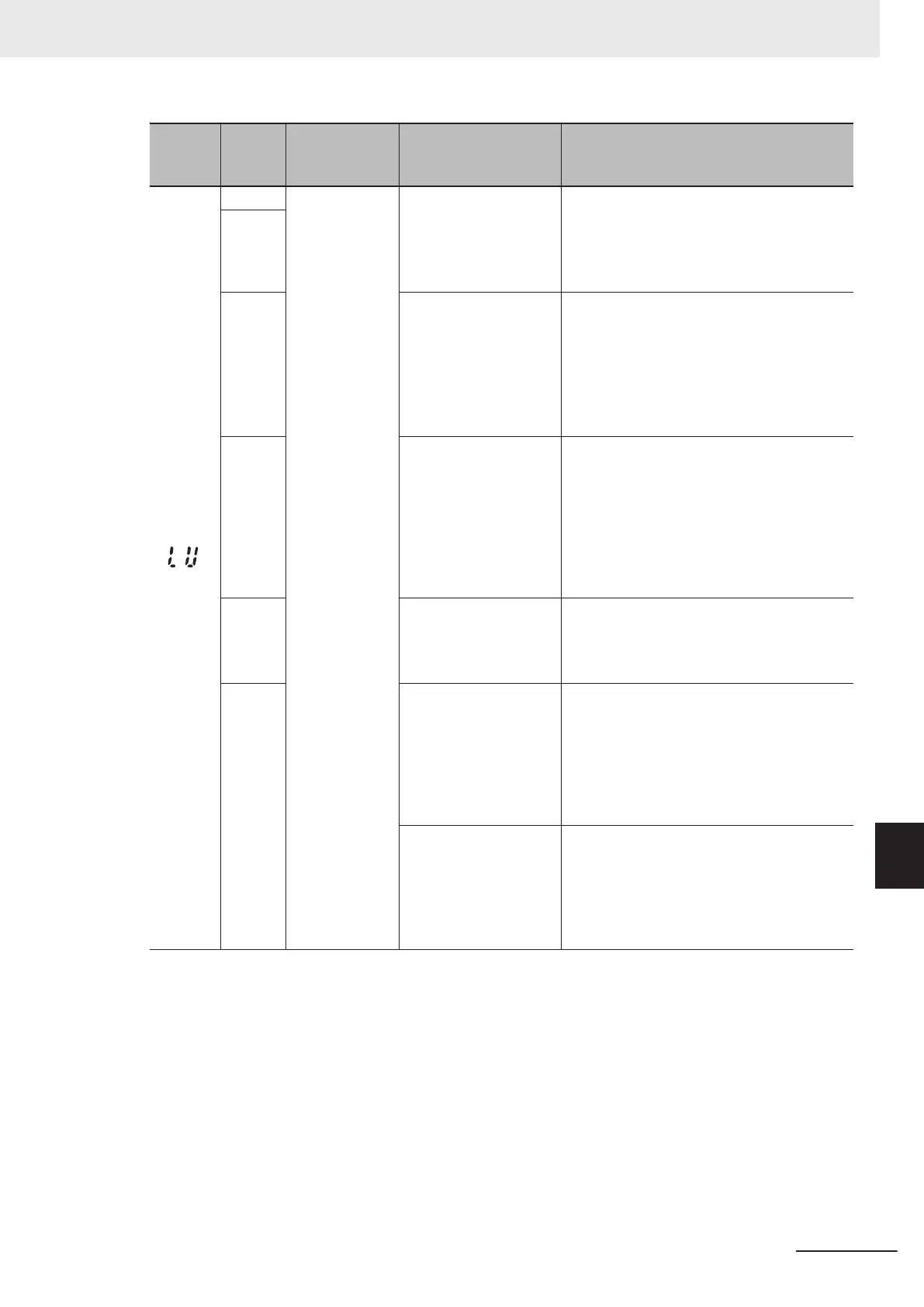
Alarm
code
Alarm
sub-
code
Name Description Check point and remedy reference
(LU)
1
Undervoltage
(1) Momentary power
failure occurred
→ Cancel the alarm.
3
→ To restart without an alarm, set the
Power Interruption Restart Mode Selec-
tion (F14) data to 3, 4, or 5 depending
on the type of load.
2
(2) Short interval when
cycling power (if F14=1)
Check if the power supply has been turned
ON with the control power supply already
ON (determine using Digital Operator dis-
play).
→ Turn the power supply ON again after
the Digital Operator display has gone
out.
(3) The power supply
voltage has not
reached the inverter
specification range
(three-phase 200 V:
180 VDC/three-phase
400 V: 360 VDC/single-
phase 200 V
: 160 VDC)
Measure the input voltage.
→ Increase the power supply voltage to
within the specified range.
(4) Equipment damage
or miswiring in power
supply circuit
Measure the input voltage and identify the
damaged equipment or miswiring.
→ Replace damaged equipment, or repair
miswiring.
(5) A large starting cur-
rent flows to a dif
ferent
load connected to the
same power supply
,
and the power supply
voltage temporarily
drops
Measure the input voltage, and check for
voltage fluctuations.
→
Review the power supply system.
(6) Insufficient capacity
in the power supply
transformer resulting in
drop in power supply
voltage due to inverter
inrush current.
Check that an alarm occurs when the mold-
ed case circuit breaker, ground leakage cir-
cuit breaker (with overcurrent protection
function), and magnetic contactor are on.
→ Review the power supply transformer
capacity.
9 Troubleshooting
9-15
M1 Series Standard Type User's Manual (I669)
9-1 Alarm Display and Remedies
9
9-1-2 Alarm Code List
 Loading...