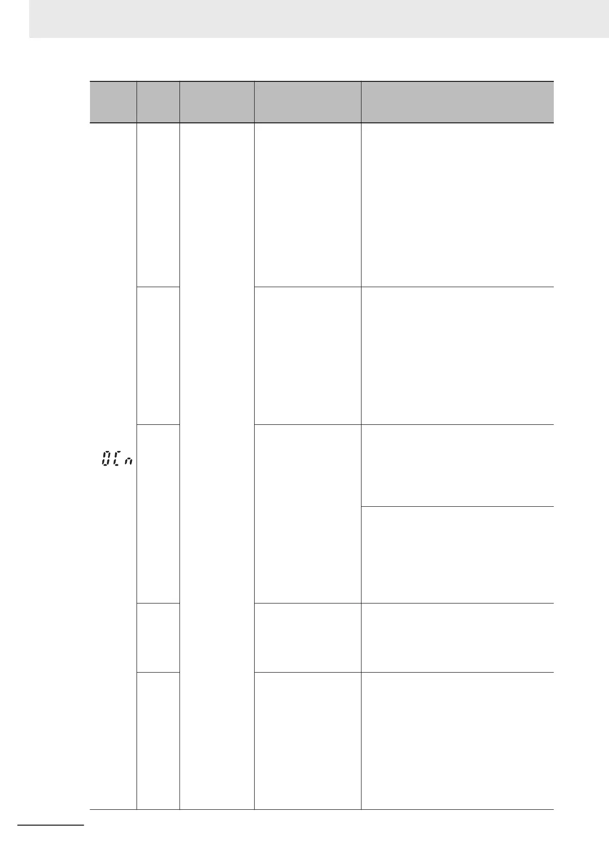
Alarm
code
Alarm
sub-
code
Name Description Check point and remedy reference
(0Cn)
Instantaneous
overcurrent
(1) Short in inverter out-
put
Remove wiring from the inverter output ter-
minal (U, V, W), and measure the resistance
between motor wiring phases. Check for
phases with very low resistance.
→ Remove the shorted section (including
replacement of wiring, relay terminals,
and motors)
If an overcurrent is displayed when run with
wiring removed from the inverter output ter-
minal (U, V, W).
→ This indicates an inverter fault possibili-
ty. Please contact OMRON.
(2) Inverter output ter-
minal has a ground
fault
Remove wiring from the inverter output ter-
minal (U, V, W), and perform a megger test.
→ Remove ground faults (including re-
placement of wiring, relay terminals,
and motors).
If an overcurrent is displayed when run with
wiring removed from the inverter output ter-
minal (U, V, W).
→ This indicates an inverter fault possibili-
ty. Please contact OMRON.
(3) High load Measure current going in to the motor, estab-
lish current trends, and determine if this is
larger than the load calculation values de-
signed in to the system.
→
If overload, either decrease the load or
increase the inverter capacity
.
Check current trends, and check if there are
rapid changes in current.
→ If the current changes rapidly
, either de-
crease the load or increase the inverter
capacity.
→ Enable instantaneous overcurrent limit-
ing (H12=1).
(4) Thigh torque boost
(If manual torque boost
(E112*/E113*=0))
Check if the current drops when 1st Manual
T
orque Boost Voltage (F09*) is reduced, or if
there is a stall.
→ If it is determined that there is no stall,
lower F09*.
(5) Short acceleration/
deceleration time
Recalculate torque required from the mo-
ment of inertia of the load and acceleration/
deceleration time, and determine if appropri-
ate.
→ Lengthen the acceleration/deceleration
time (F07, F08, E10 to E15, H56).
→ Enable 1st Overload Protect Function
Selection (F43) and torque limit (F40,
F41, E16, E17).
→ Increase the inverter capacity.
9 Troubleshooting
9-16
M1 Series Standard Type User's Manual (I669)
 Loading...