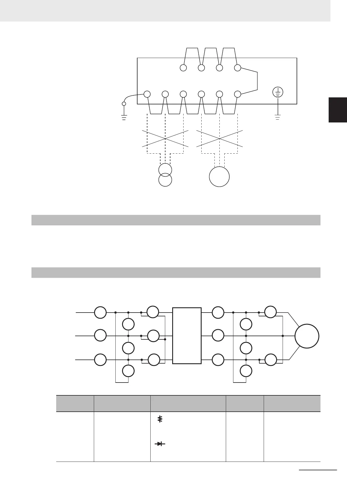
L1/R L2/S L3/T U V W
DB
IM
P1 P(+) N(-)
500-VDC megger
Do not connect
the power supply wires.
Do not connect to the motor.
Power supply Motor
Ground
terminal
10-1-6
Withstand Voltage Test
Do not conduct a withstand voltage test on any part of the inverter.
Doing this test is dangerous because it may cause damage to or deterioration of the parts inside the
inverter.
10-1-7
I/O Voltage/Current/Electric Power Measurement Method
Measuring instruments commonly used for input/output voltage, current, or electric power measure-
ment are shown below.
I R
I S
I T
ER
ET
ES
WI2
WI3
WI1
R
T
S
U
V
W
I U
I V
I W
EU
EW
EV
WO2
WO1
W
V
U R
S
T
Power
supply
Inverter
Motor
Measure-
ment item
Measurement point Measuring instrument Remarks
Measurement value
reference
Power supply
voltage
E
IN
Between L1/R and
L2/S (E
R
)
Between L2/S and
L3/T (E
S
)
Between L3/T and
L1/R (E
T
)
Moving-iron voltmeter
or rectifier type volt-
meter
All effective
values
200-V class: 200 to
240 V, 50/60 Hz
400-V class: 380 to
480 V, 50/60 Hz
10 Maintenance and Inspection
10-7
M1 Series Standard Type User's Manual (I669)
10-1 Maintenance and Inspec-
tion
10
10-1-6 Withstand Voltage Test

 Loading...


