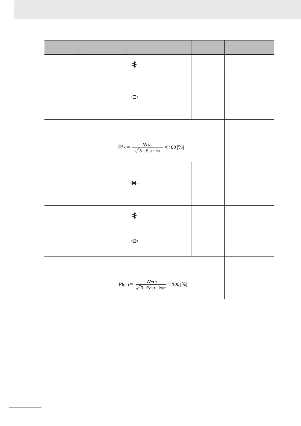
Measure-
ment item
Measurement point Measuring instrument Remarks
Measurement value
reference
Power supply
current
I
IN
Current in L1/R, L2/S,
L3/T (I
R
), (I
S
), (I
T
)
Moving iron ammeter
All effective
values
When input current is
not balanced:
I
IN
= (I
R
+I
S
+I
T
)/3
Input electric
power
W
IN
Between L1/R and
L2/S (W
I1
)
Between L2/S and
L3/T (W
I2
)
Between L3/T and
L1/R (W
I3
)
Electrodynamic watt-
meter
All effective
values
Three-wattmeter
method
(W
I1
) + (W
I2
) + (W
I3
)
Input power
factor
Pf
IN
Calculate this from the measured values of power supply voltage E
IN
,
power supply current I
IN
, and input electric power W
IN
.
-
Output volt-
age
E
OUT
Between U and V
(E
U
)
Between V and W
(E
V
)
Between W and U
(E
W
)
Refer to the figure on
the next page, or rec-
tifier type voltmeter.
Effective val-
ue of funda-
mental wave
-
Output cur-
rent
I
OUT
Current of U, V and W
(I
U
), (I
V
), (I
W
)
Moving iron ammeter
All effective
values
-
Output power
W
OUT
Between U and V
(W
O1
)
Between V and W
(W
O2
)
Electrodynamic watt-
meter
All effective
values
Two-wattmeter meth-
od (or three-wattme-
ter method) (W
O1
) +
(W
O2
)
Output power
factor
Pf
OUT
Calculate this from the measured values of output voltage E
OUT
, out-
put current I
OUT
, and output electric power W
OUT
.
-
Note 1. For the output voltage, use a measuring instrument that shows effective values of fundamental wave.
For the current and the electric power, use a measuring instrument that shows all effective values.
Note 2. The output waveform of the inverter has a margin of error
, especially at low frequencies, because it was
generated under PWM control. Note that many general-purpose testers may not be usable due to noise.
10 Maintenance and Inspection
10-8
M1 Series Standard Type User's Manual (I669)

 Loading...


