• For compliance with the UL standard requirements, be sure to perform wiring according to
2-4-3 UL/cUL Standards Cautions on page 2-76, which includes the use of UL-compliant specified
fuses and specified wiring materials.
• T
ighten the terminal block screws with the specified torque. Weak tightening may result in a short-
circuiting accident or fire. Conversely, overtightening these screws may cause damage to the termi-
nal block or the inverter.
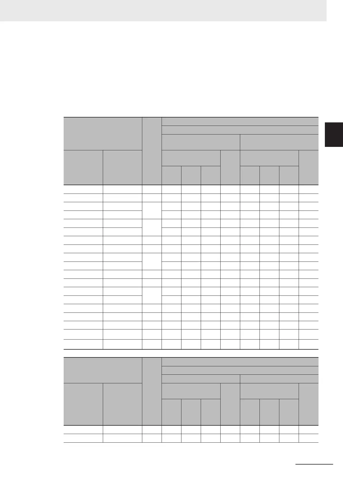
Three-phase 200-V class (Panel internal temperature 50°C or less)
Model
Maxi-
mum
appli-
cable
motor
ca-
paci-
ty
[kW]
Recommended wire size [mm2]
Main power supply input (L1/R, L2/S, L3/T)
When DC reactor (DCR) is
used
Without DC reactor
HHD mode HND mode
Allowable tempera-
ture (Note 1)
Cur-
rent
value
[A]
Allowable tempera-
ture (Note 1)
Cur-
rent
value
[A]
60°C 75°C 90°C 60°C 75°C 90°C
3G3M1-A2001 - 0.1 2.0 2.0 2.0 0.6 2.0 2.0 2.0 1.1
3G3M1-A2002 3G3M1-A2001 0.2 2.0 2.0 2.0 0.9 2.0 2.0 2.0 1.8
- 3G3M1-A2002 0.4 2.0 2.0 2.0 1.6 2.0 2.0 2.0 2.6
3G3M1-A2004 - 2.0 2.0 2.0 1.6 2.0 2.0 2.0 3.1
- 3G3M1-A2004 0.75 2.0 2.0 2.0 3.0 2.0 2.0 2.0 4.9
3G3M1-A2007 - 2.0 2.0 2.0 3.0 2.0 2.0 2.0 5.3
- 3G3M1-A2007 1.1 2.0 2.0 2.0 4.3 2.0 2.0 2.0 6.7
3G3M1-A2015 - 1.5 2.0 2.0 2.0 5.7 2.0 2.0 2.0 9.5
- 3G3M1-A2015 2.2 2.0 2.0 2.0 8.3 2.0 2.0 2.0 12.8
3G3M1-A2022 - 2.0 2.0 2.0 8.3 2.0 2.0 2.0 13.2
- 3G3M1-A2022 3 2.0 2.0 2.0 11.7 3.5 2.0 2.0 17.9
3G3M1-A2037 - 3.7 2.0 2.0 2.0 14.0 5.5 2.0 2.0 22.2
- 3G3M1-A2037 5.5 3.5 2.0 2.0 19.9 8.0 3.5 2.0 28.5
3G3M1-A2055 - 5.5 2.0 2.0 21.1 8.0 3.5 3.5 31.5
3G3M1-A2075 3G3M1-A2055 7.5 8.0 3.5 2.0 28.8 14.0 5.5 5.5 42.7
3G3M1-A2110 3G3M1-A2075 11 14.0 5.5 5.5 42.2 22.1 14.0 8.0 60.7
3G3M1-A2150 3G3M1-A2110 15 22.0 14.0 8.0 57.6 38.0 14.0 14.0 80.0
3G3M1-A2220 3G3M1-A2150 18.5
38.0
*1
14.0 14.0 71.0
60.0
*2
22.0 14.0 97.0
- 3G3M1-A2220 22
38.0
*1
22.0 14.0 84.4
60.0
*2
38.0
*1
22.0 112.0
Model
Maxi-
mum
appli-
cable
motor
ca-
paci-
ty
[kW]
Recommended wire size [mm2]
Inverter output (U, V, W)
HHD mode HND mode
HHD mode HND mode
Allowable tempera-
ture (Note 1)
Cur-
rent
value
[A]
Allowable tempera-
ture (Note 1)
Cur-
rent
value
[A]
60°C 75°C 90°C 60°C 75°C 90°C
3G3M1-A2001 - 0.1 2.0 2.0 2.0 1.0 - - - -
3G3M1-A2002 3G3M1-A2001 0.2 2.0 2.0 2.0 1.6 2.0 2.0 2.0 1.3
2 Design
2-19
M1 Series Standard Type User's Manual (I669)
2-3 Wiring
2
2-3-4 Wiring for Main Circuit Terminals

 Loading...


