A-4
Overview of Inverter Selection
A-4-1
Motor Capacity Selection
Before selecting an inverter, first the motor should be chosen. In selecting the motor, calculate the load
inertia appropriate to the application, and then calculate the required capacity and torque.
Simplified Selection Method (Required Output Calculation)
This method of calculation helps you select a motor by calculating the output (kW) required by the mo-
tor to maintain its steady rotations. To use this method for motor selection, make allowance for the cal-
culated result because it does not include acceleration/deceleration and other transient state calcula-
tions. The simplified selection method is suitable for fan, conveyor, mixer and other applications where
a constant state continues for a while.
Note
The simplified selection method cannot be used for the following applications. For these applications, use
the detailed selection method.
• Those requiring rapid startup (acceleration).
• Those that frequently repeat run and stop.
• Those that have a large inertia at the power transfer part.
• Those that have an inefficient power transfer part.
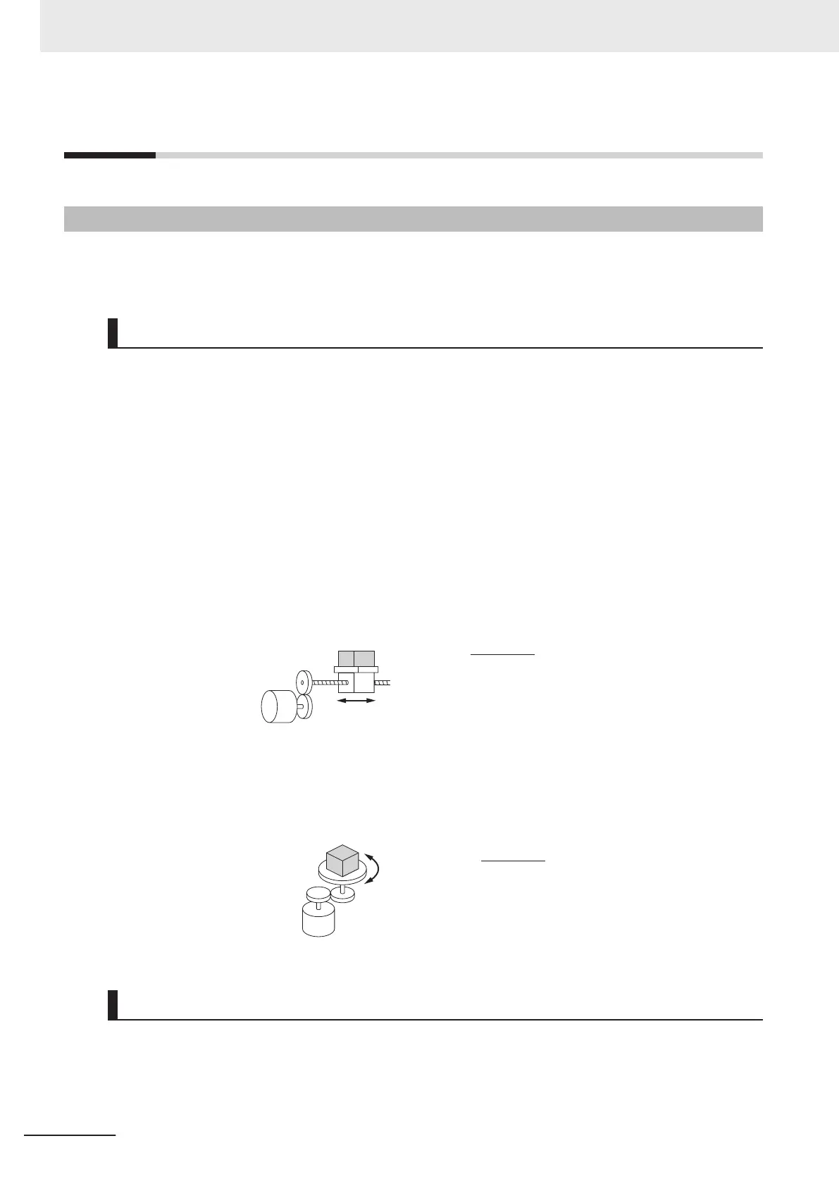
For linear motion: Steady power P
0
[kW]
Motor
η
V
l
M
P0 [kW] =
μ : Friction coefficient
M : Mass of linear motion part [kg]
g : Acceleration of gravity (g ≈ 9.8 [m/s
2
])
Vl : Speed of linear motion part [m/min]
η : Efficiency of transfer part (η ≤ 1)
× 10
-3
μ
μ · Mg · Vl
6
0 · η
Note
The same calculating formula is applicable to belt conveyors.
For rotation motion: Steady power P
0
[kW]
60 · η
2π ·Tl ·Nl
× 10
-
3
Tl : Load torque (Load shaft) [N·m]
Nl : Rotation speed of load shaft [r/min]
η : Efficiency of transfer part (η ≤ 1)
P0 [kW] =
Motor
η
Tl
Nl
Detailed Selection Method (RMS Calculation)
This method helps you select a motor by calculating the effective torque and maximum torque values
required to achieve a certain pattern of operation for the application. It selects a motor that is optimal
for a particular operation pattern.
Appendix
A-10
M1 Series Standard Type User's Manual (I669)

 Loading...


